DLPU113A December   2021  ā€“ April 2022 DLP2021-Q1


  1.   Trademarks
  2. 1DLP2021-Q1 Electronics EVM Overview
    1. 1.1 Introduction
    2. 1.2 What is in the DLP2021-Q1 Light Engine EVM
      1. 1.2.1 Formatter Subsystem
      2. 1.2.2 Illumination Subsystem
      3. 1.2.3 Light Engine
      4. 1.2.4 Cables
    3. 1.3 Non-Optical Specifications
      1. 1.3.1 Electrical Specifications
      2. 1.3.2 Component Temperature Ratings
      3. 1.3.3 LED Driver Design
      4. 1.3.4 Video Specification
  3. 2Quick Start
    1. 2.1 Kit Assembly Instructions
    2. 2.2 Software Installation
    3. 2.3 Power-Up
    4. 2.4 Select Display Content
    5. 2.5 LED Driver
  4. 3Optics and Mechanics
  5. 4Software
    1. 4.1 DLP Composer
      1. 4.1.1 Default Register Configuration
      2. 4.1.2 Illumination
      3. 4.1.3 Sequence Set
      4. 4.1.4 Degamma Curves
      5. 4.1.5 Image/Video
      6. 4.1.6 Flash Blocks
      7. 4.1.7 Flash Programming
    2. 4.2 DLP Control Program
      1. 4.2.1 Connection
      2. 4.2.2 Scripting
      3. 4.2.3 Registers
      4. 4.2.4 Commands
    3. 4.3 MSP430 Example Code
  6. 5Revision History

Power-Up

Follow these steps to properly supply power to the EVM:

  1. Connect the input power cable to a power supply that meets input power specifications defined in Section 1.3.1. A 12-V supply with a 0.5-A limit is recommended for out-of-box evaluation. The red cable for the V+ terminal and black cable for the Vā€“ terminal. A red LED will illuminate on the electronics board to indicate the EVM is receiving power.

  2. Set the operation mode switches to the Local Host Control operating mode as defined in Section 1.2.1. The EVM is already flash programmed with TI demo image/video content when shipped for out-of-box evaluation.
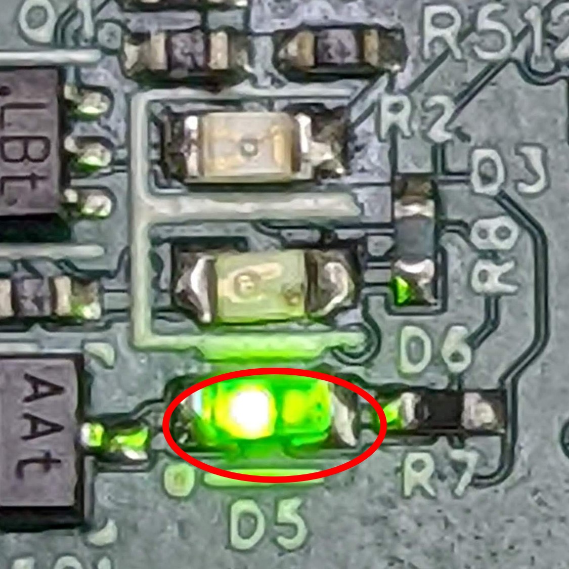
    GUID-20211206-SS0I-7BBP-VDSL-CR5BF3CHWCWC-low.jpgFigure 2-2 Local Host Operating Mode LED Status

  3. Turn on the supply power, and the EVM will immediately begin to display content.