SBAA492A September 2021 – April 2022 PCM3120-Q1 , PCM5120-Q1 , PCM6120-Q1 , TLV320ADC3120 , TLV320ADC5120 , TLV320ADC6120
2 Automatic Gain Control
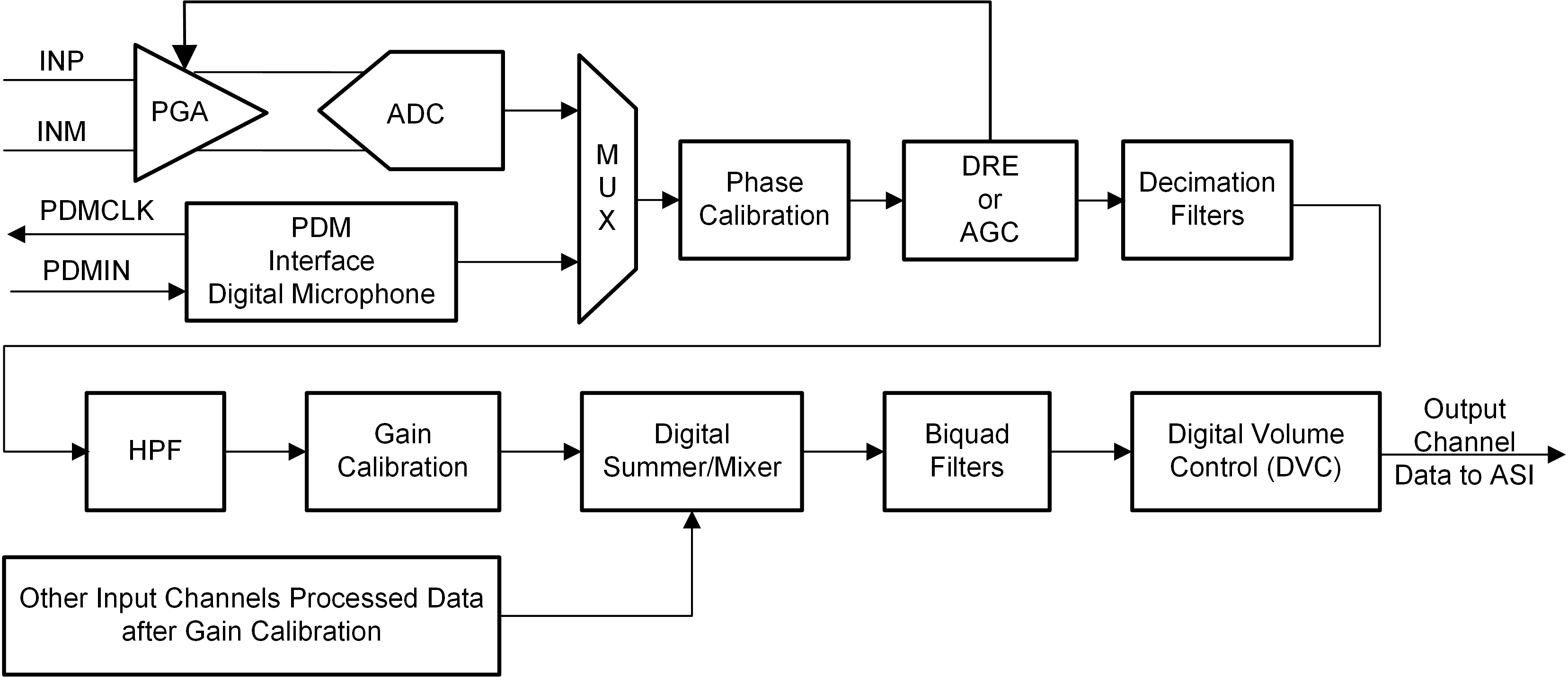
The AGC algorithm is a mixed-signal solution, where the analog programmable gain amplifier (PGA) of a channel is controlled by a closed-loop control digital algorithm. Figure 2-1 shows the signal processing chain for the device.
 Figure 2-1 AGC Block Diagram
To respond to changes in the input signal, the AGC algorithm monitors the digitized signal from the ADC and adjusts the PGA to maintain a constant target level. If the signal is below the target level, the AGC increases the PGA gain. If the signal is above the target level, the AGC decreases the PGA gain. Using the analog circuitry of the PGA to change the input signal provides optimal noise performance, since it avoids gain adjustments in the digital circuitry that increases the quantization noise. Moreover, the AGC algorithm uses a small step size during PGA changes to reduce distortions in the input signal.
The TLV320ADCx120 and PCMx120-Q1 family supports up to two analog external input channels, with all input channels supporting AGC. The devices support differential or single-ended signals from an analog microphone source or auxiliary line input. The analog microphone inputs supports electret condensers and micro-electro-mechanical (MEMS) microphones. Even though the devices also support digital pulse density modulated (PDM) digital microphones, the AGC does not support digital channels, since the analog gain of the digital microphone cannot be controlled.
The TLV320ADC5120, TLV320ADC6120, PCM5120-Q1, and PCM6120-Q1 also support a Dynamic Range Enhancer (DRE) algorithm on the analog channels to augment the dynamic range. The DRE algorithm controls the PGA to reduce the noise floor for low-level signals. DRE and AGC algorithms cannot be used simultaneously, since both the algorithms control the PGA. As shown in Table 2-1, DRE or AGC selection is done using the DRE_AGC_SEL bit of DSP_CFG1 register (page = 0x00, address = 0x6C). AGC or DRE can be independently enabled or disabled for each channel using the CH1_DREEN (P0_R60_D0), CH2_DREEN (P0_R65_D0), CH3_DREEN (P0_R70_D0), and CH4_DREEN (P0_R75_D0) register bits.
| BIT | FIELD | TYPE | RESET | DESCRIPTION |
|---|---|---|---|---|
| 3 | DRE_AGC_SEL | R/W | 0h | DRE or AGC selection when is enabled for any channel. 0d = DRE is selected. 1d = AGC is selected. |