SBAA548A April 2022 – May 2022 ADS8588S , ADS8681 , ADS8686S , ADS8688 , ADS8688A
3.4 Conducted Immunity (CI)
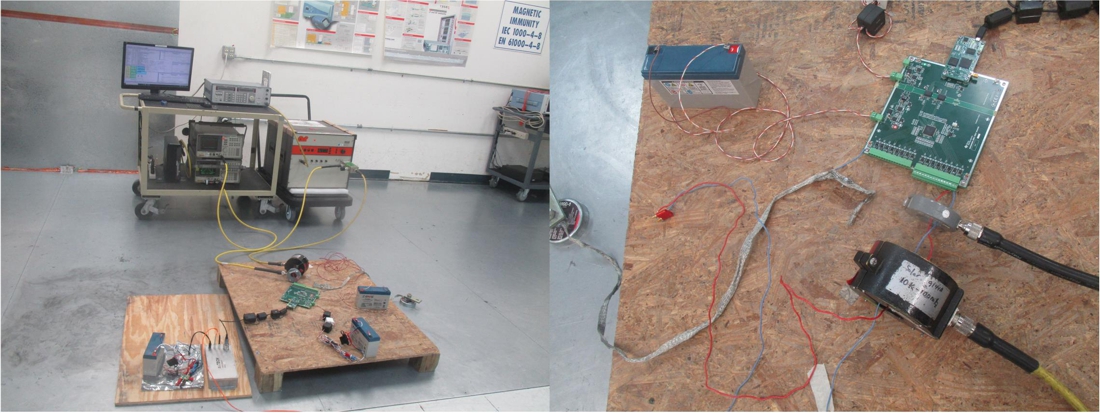
The IEC 61000-4-6 standard specifies the details about the conducted immunity test. The test is to verify the EUT immunity to conducted electromagnetic disturbances induced onto the EMC board input terminals. The test signal is generated from an RF signal generator and RF power amplifier equipment is used to amplify the test signal to a specified level. The test signal is injected to the EMC board input with an injection probe. The spectrum analyzer 1 is used to monitor the output of the power amplifier, and the spectrum analyzer 2 is used to monitor and verify the injected signal with a monitoring probe. The signal frequency is swept from 150 kHz to 80 MHz with a disturbance signal of 80% amplitude that is modulated with a 1-kHz sinusoidal signal. Two field strength levels are applied and tested: 3 V/m and 10 V/m.
Figure 3-9 shows a photograph of the actual setup for the conducted immunity test.
 Figure 3-9 Photograph of Laboratory Setup for Conducted Immunity Test
Table 3-4 shows the results of the conducted immunity test.
| Test | IEC Standard | Test Signal | Test Level | Criterion | Test Result | |
|---|---|---|---|---|---|---|
| Field Strength | Frequency | |||||
Conducted Immunity (CI) | IEC 61000-4-6 | 3 V/m | 150 kHz–80 MHz | 2 | A | Pass |
| 10 V/m | 150 kHz–80 MHz | 3 | A | Pass | ||