SBAU382A November 2021 – January 2022 ADS7029-Q1 , ADS7039-Q1 , ADS7040 , ADS7041 , ADS7042 , ADS7043 , ADS7044 , ADS7046 , ADS7047 , ADS7049-Q1 , ADS7052 , ADS7054 , ADS7056 , ADS7057
4.5 Histogram Analysis
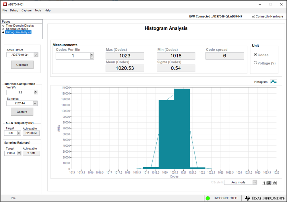
Noise degrades ADC resolution and the Histogram Analysis tool can be used to visualize the ADC noise performance. Noise couples to the ADC output from sources such as the input drive circuits, the ADC power supply, and the ADC itself. The cumulative effect of this noise is reflected in the standard deviation of the ADC output code histogram obtained by performing multiple conversions of a DC input. As shown in Figure 4-5, click the Capture button to display a histogram corresponding to a DC input.
 Figure 4-5 Histogram Analysis in the ADS704X-5XEVM GUI