SBOA518 January 2022 TMCS1100 , TMCS1100-Q1 , TMCS1101 , TMCS1101-Q1 , TMCS1107 , TMCS1107-Q1 , TMCS1108 , TMCS1108-Q1
5.2 Conduction Paths
Another somewhat unavoidable source of magnetic fields is any current-carrying wire, which includes all surrounding PCB traces and wires as well as the input lines into the Hall-sensing device. Consequently, more attention must be devoted to layout than that of a conventional current shunt monitor. The amount of field a current-carrying wire imposes upon the Hall-sensing element of the device can be determined mathematically via Ampere's Law, given in Equation 8.
This equation requires the magnitude of the current carried in the wire under analysis, as well as the orthogonal distance of the wire to the sensor located in the TMCS110x device. This equation allows for the approximation of the external field generated by wires or traces, and may be useful for creating design rules for PCB layout that ensure that traces remain a certain distance away from the sensor to ensure optimization of the generated field.
For example, consider a trace on a PCB located 15 mm from a TMCS1101. For the TMCS110x family, the location of the sensor may be approximated as the center of the package. Examining the data sheet for D0008B package information, the worst case distance to the outer footprint of the package is 2.9 mm, taking the pins of the device into account. This is visualized in Example - Distance From Trace to Sensor.
Equation 9 and Equation 10 show that the contribution from this trace at this distance is potentially 33.5 µT in the positive z direction at the point of the sensor, or a –30.45 mA offset current referred to the input. Also, note that this calculation needs to be performed for each trace in proximity to the TMCS110x, as each current-carrying conductor exhibits an influence on the sensor. Right hand rule should also be taken into account, because the directionality of current flow also dictates the polarity of the contributed field.
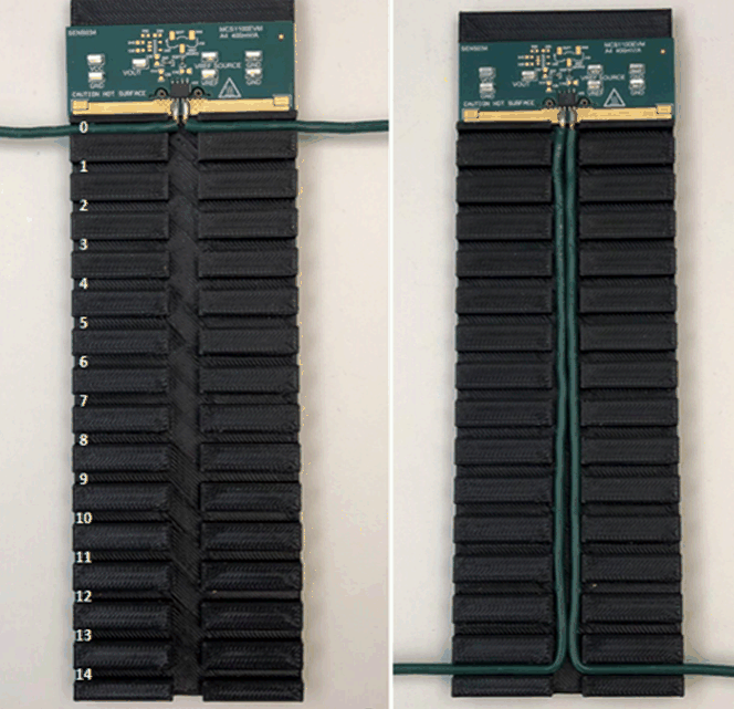
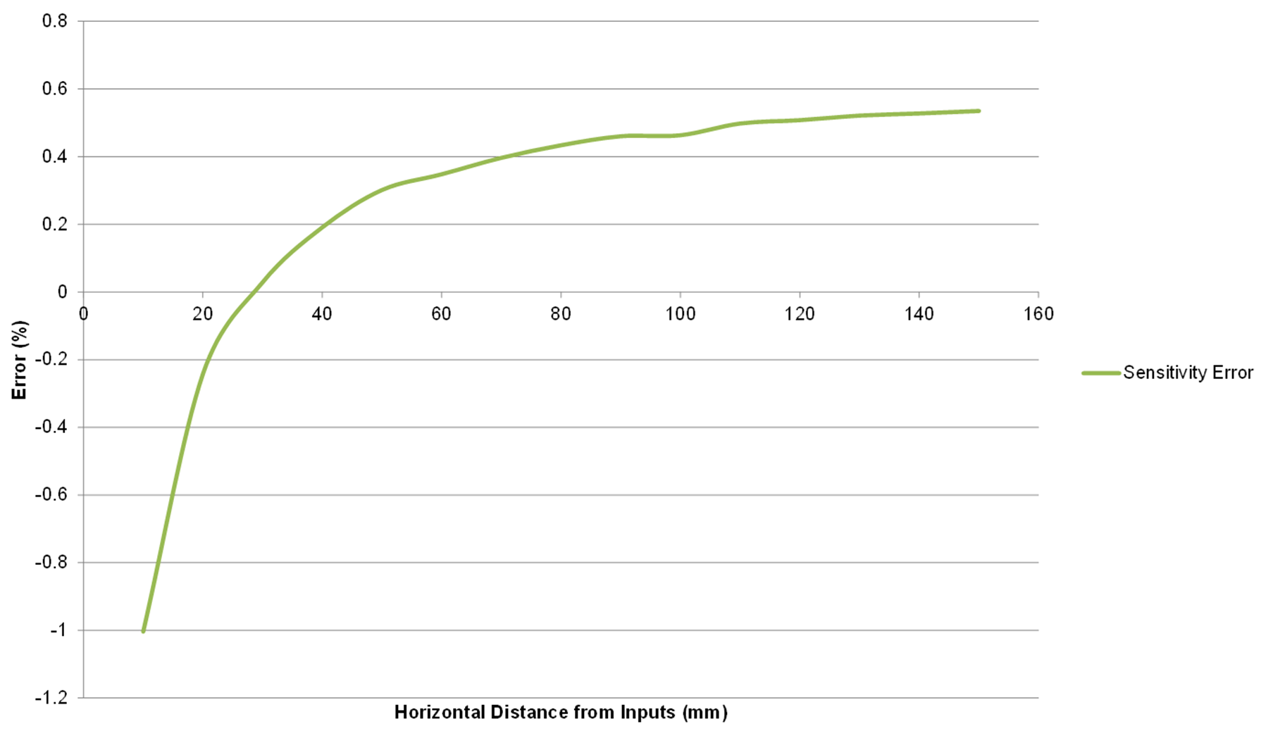
While it is straightforward to isolate high current traces from the TMCS110x, a more challenging observation is that the input current approach external to the device also has the potential to contribute an external field. To examine the effects of this, a 3D printed structure was created to insert an insulated wire pair at fixed 10-mm intervals from the TMCS1100EVM. TMCS1101 Bifurcation Test Board shows the construction of the 3D printed housing and test set up. Data was captured via this setup for a typical device, and TMCS1101 Bifurcation Test Results shows the typical effects of the proximity of these wires across a range from 10 mm to 150 mm from the input pins of the device.
 Figure 5-3 TMCS1101 Bifurcation Test
Board
 Figure 5-4 TMCS1101 Bifurcation Test
Results
Figure 5-4 TMCS1101 Bifurcation Test
ResultsObservation indicates that the external field shifts the error of the TMCS1101 as the traces approach the device, and minimizes their contribution as the traces move further away from the device. Also note that from these observations the recommended angle of approach for the TMCS110x family is directly into the pins of the device for best performance. This is demonstrated on the TMCS1100EVM and TMCS1101EVM. Deviation away from a head-on approach may require layout calibration for optimized results. See the Calibration section for additional details.