SBOA544 May 2022 TRF1208
3 Why use a Fully Differential Amplifier?
A fully differential amplifier (FDA) provides an active gain component while providing the same benefits as a balun, potentially reducing the overall BOM count and the board space for the RF signal chain. However, an FDA does require a power supply and adds noise to the passing signal, and may cause the phase imbalance to become more pronounced.
Figure 3-1 shows an FDA configured in three different typologies, a differential-to-differential, a single-ended-to-differential, and a differential-to-single-ended setup, allowing engineers to accommodate multiple RF configuration needs with a single device.
Figure 3-1 Different Configurations With an FDA
In Figure 3-2, an FDA is configured as a single-ended-to-differential amplifier and can be used to replace a single-ended gain amplifier and a passive balun to interface with the ADC as shown in Figure 2-1.
Figure 3-2 Simplified Schematic of a Fully Differential Amplifier Interacting With an ADC
Inherently, amplifiers and gain blocks are single-ended and will provide poor phase imbalance and higher even-order distortion. For example, analog inputs of ADCs are typically a differential interface, the two inputs are ideally required to be equal in amplitude and 180-degrees out of phase. However, maintaining this balanced signal can be quite challenging. As these two input signals slip away from ideal 180-degrees, this produces a phase shift, which generates a common-mode signal, causing even-order distortion (HD2) to become more pronounced.
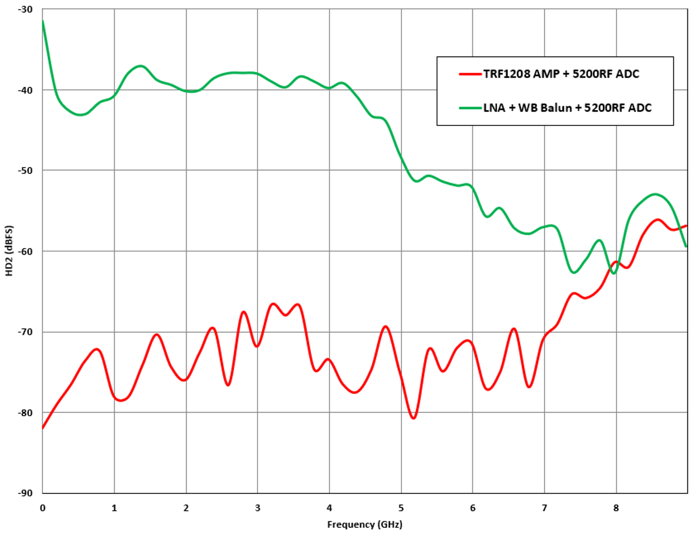
Specifically, for wideband applications, the TRF1208 (a single-channel, 10-MHz to 11-GHz, 3-dB bandwidth, single-ended to differential RF amplifier in a small 4-mm2 QFN package) provides superior gain and phase imbalance of ±0.3 dB and ±3 degrees, which is competitive with the best passive wideband baluns on the market. In Figure 3-1, the TRF1208 combined with the ADC12DJ5200RF provides a 2nd order harmonic distortion lower than –60 dBFS up to 8 GHz. With a discrete wideband low-noise amplifier (LNA) and passive balun solution, the amplifier can be the limiting factor for linearity and ultimately cause unwanted higher HD2 performance as seen in Figure 3-3. The TRF1208 provides up to –30 dBFS better in HD2 performance than a competitor LNA and balun solution.

Figure 3-3 Second Order Harmonic Distortion (HD2) Performance of TRF1208 (FDA) and ADC12DJ5200RF (ADC) vs a Wideband LNA and Balun Solution
Matching a wideband ADC to a single-ended source can be a difficult challenge, especially at frequencies above the fundamental Nyquist zone. The input impedance of an ADC is typically much higher than 50 Ω, generally 100 Ω or in the kΩ range. This means that a higher output impedance balun will typically match better to an ADC input than a 1:1 balun. Due to the band-limiting nature of the ADC, it is often necessary to use a balun that is much wider band in a pure 50-Ω system than the required system bandwidth. However, passive baluns can become larger in size, the lower frequency the system goes, causing the single-ended amplifier and balun solution to increase the total system size.
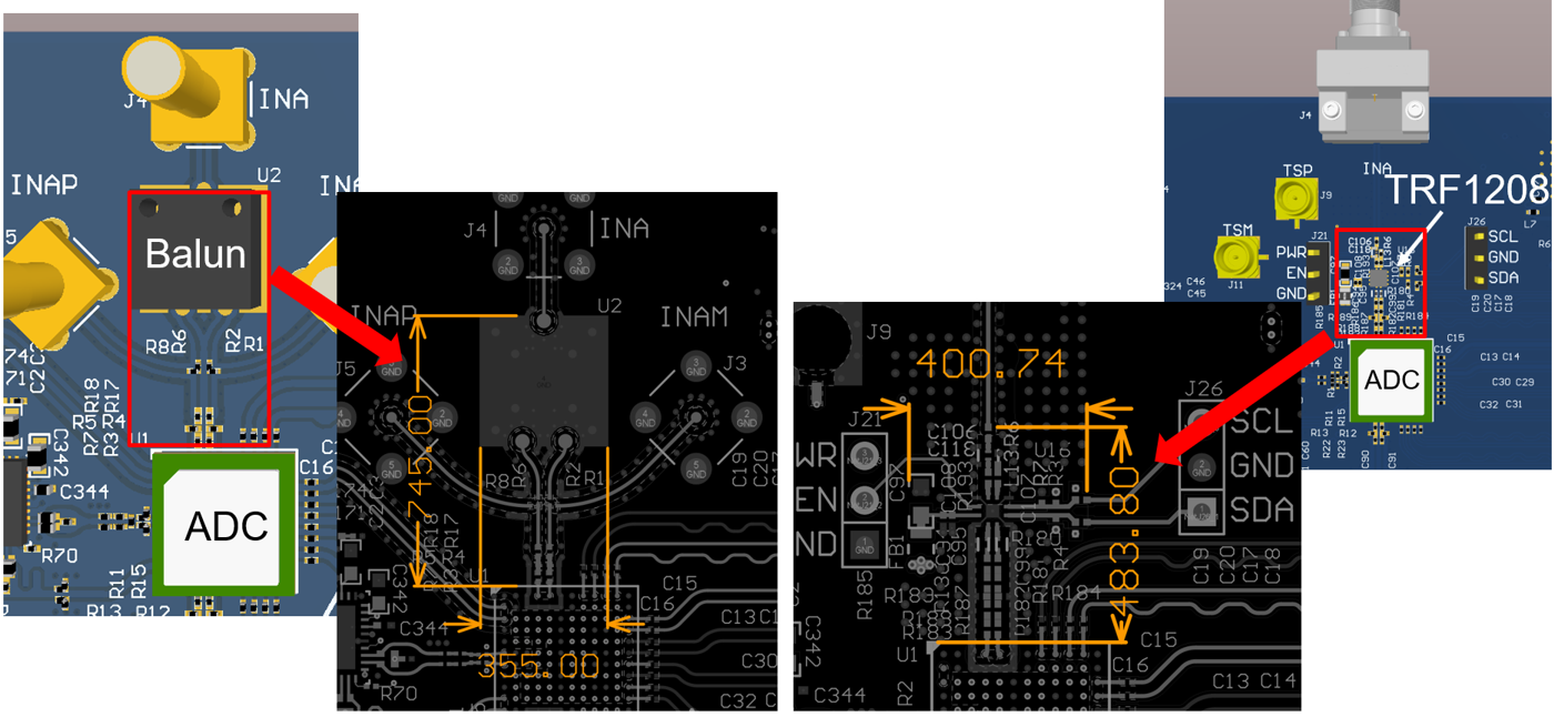
Figure 3-4, shows that a balun and gain block solution that covers a frequency range up to 12 GHz is a significantly larger solution size than an FDA, such as the TRF1208. The TRF1208 is housed in a 4-mm2 QFN package with an overall board solution size of 120 mm2 versus mechanically built baluns that can reach package sizes greater than 64 mm2 and the board space usage can average around 171 mm2. With the addition of a gain block to the balun solution, the board space can approach 200 mm2 of PCB area.

Figure 3-4 Solution Size Comparison Of Surface-Mount Broadband Balun and TRF1208