SBVU067A April 2020 – June 2021 TPS62840
1.2.3 Loop Response Measurement
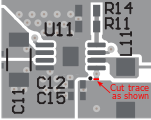
The loop response of the EVM can be measured with two simple changes to the circuitry. First, cut the trace between the VOS pin and the output capacitor on the top layer. This change is shown in Figure 1-1. Second, install a 10-Ω resistor across the resistor pads on the back of the PCB at Rx2. The pads are spaced to allow installation of an 0603-sized resistor. With these changes, an ac signal (10-mV, peak-to-peak amplitude is recommended) can be injected into the control loop across the added resistor. Details of measuring the control loop of DCS-Control devices are found in the How to Measure the Control Loop of DCS-Control™ Devices application report.
 Figure 1-1 Loop Response Measurement Modification