SLAA871 January   2019 AFE7422 , AFE7444


  1.   AFE74xx as a single-chip wideband repeater using loopback mode
    1.     Trademarks
    2. 1 Introduction
    3. 2 Repeater Mode (RX-TX Loopback With SerDes Bypassed)
      1. 2.1 Overview of the AFE74xx Repeater Mode
      2. 2.2 Configuration of the AFE74xx as a Repeater
      3. 2.3 Programming the Repeater Mode
        1. 2.3.1 Hardware Setup
        2. 2.3.2 Software Setup and GUI Configuration
    4. 3 130-MHz Digital Repeater System Overview
      1. 3.1 Key System Specifications
    5. 4 System Overview
      1. 4.1 Block Diagram
      2. 4.2 Design Considerations
      3. 4.3 Highlighted Products
        1. 4.3.1 LMK04828
      4. 4.4 System Design Theory
    6. 5 Hardware and Testing
      1. 5.1 Measured Latency and Gain
        1. 5.1.1 Hardware
        2. 5.1.2 Test Setup and Results
      2. 5.2 Measured Linearity Performance
        1. 5.2.1 Hardware and Test Setup
        2. 5.2.2 Test Results
      3. 5.3 Measured Selectivity (Out-of-Band Jammer)
        1. 5.3.1 Hardware and Test Setup
        2. 5.3.2 Test Results
    7. 6 Terminology

Test Setup and Results

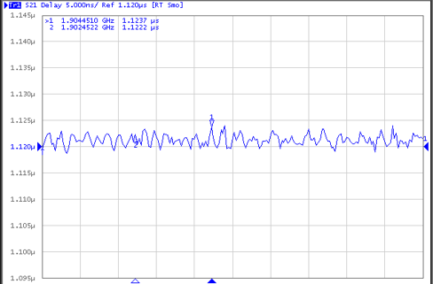
Figure 12 shows the setup. Port 1 drives the input of the repeater with frequencies ranging from 1900 MHz to 1920 MHz, and port 2 receives the signals from port 1, documenting the time of flight from Port 1 to Port 2. The average group delay is approximately 1.12 µs. Figure 13 shows a graph of latency as a function of frequencies between 1900 MHz and 1920 MHz.

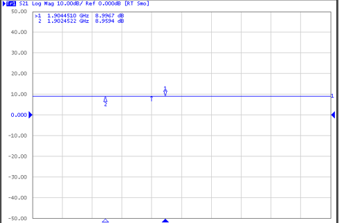
The maximum gain was determined using the same setup as group delay and is approximately 9 dBm when both of the RX and TX DSA settings are set to 0. Figure 14 shows a graph of gain verses frequencies between 1900 MHz and 1910 MHz.

tida-060007-latency-gain-test-setup.gifFigure 12. Latency and Gain Test Setup
tida-060007-figure-x-latency-measurement-average-latency-=-1.12-us-scope-shot.png
Figure 13. Latency Measurement,
Average Latency = 1.12 µs
tida-060007-figure-x-gain-measurement-gain-is-flat-at-9-dbm-with-txrx-dsa-set-to-0-scope-shot.png
Figure 14. Gain Measurement: Gain is Flat at 9 dBm
With TX/RX DSA Set to 0