SLAA952 July 2020 – MONTH TAS2563
1.13 Step 13: Thermal Modeling
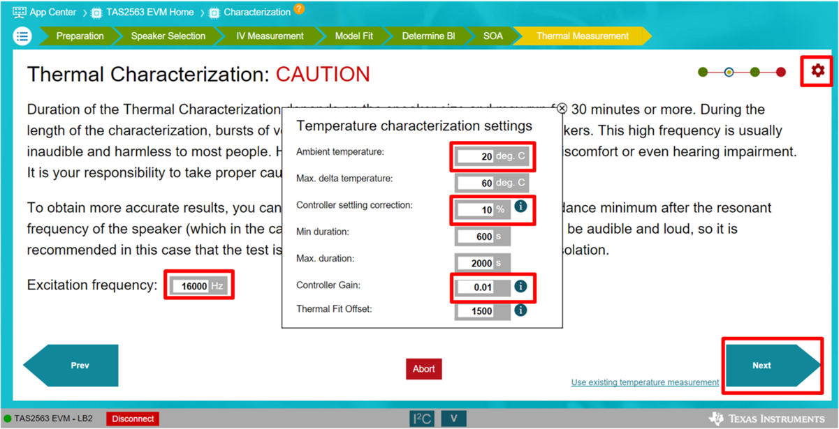
Define the excitation frequency to test the speaker. Depending on the impedance characteristic of each speaker, excitation frequency required may change. The default excitation frequency is 16 kHz; however lower frequency (e.g. 3 kHz) may leads to more accurate result. Select “Next” to continue
Select the Option icon in the upper-right corner to access more settings.
“Ambient temperature” can be changed to the room temperature which the device is under testing.
“Max. delta temperature” was defined previously in the Safe Operating Area tab as “ΔThermal Limit”
Min. and Max duration define the runtime of the thermal measurement test and should be left in default values.
For larger speakers, the “Controller setting correction” and “Controller Gain” may need to be increased. For example, for speakers with power rating of 1 W, use a controller gain of 0.01, and for speakers with power rating between 2 W to 3 W, change the controller gain to 0.03
Thermal Fit Offset is usually set as default.
In case of oscillatory behavior during temperature test, it is recommended to run with lower controller gain for a more stable response.
In order to properly test the thermal characteristic, please wait at least 30 minutes before performing the thermal characterization test again on the same speaker unit. This will ensure the speaker coil has time to cool down and reach ambient temperature.
 Figure 1-15 Thermal Characterization.
 After this page, the device will run several cycles of temperature test with loud tone (set by the excitation frequency).