SLAAE97A March 2023 – September 2023 MSPM0L1105 , MSPM0L1106 , MSPM0L1303 , MSPM0L1304 , MSPM0L1304-Q1 , MSPM0L1305 , MSPM0L1305-Q1 , MSPM0L1306 , MSPM0L1306-Q1 , MSPM0L1343 , MSPM0L1344 , MSPM0L1345 , MSPM0L1346
Optimized H-Bridge Driver Control for Stepper and Brushed-DC (BDC) Motors Using MSPM0 MCUs
In the modern world, motors are used in many products. Stepper motors are widely used in slide rails, workbenches, medical machines, and many other applications because of small size, low cost, position control, ease of use, and no cumulative error. Brushed DC (BDC) motors are also widely used in lathes, starters, and electric locomotives because of good starting and speed performance. For these two kinds of motors, the H-bridge structure is used in hardware to control the speed and direction of the motor. MSPM0 MCUs can fill this role with a broad portfolio, abundant analog features, and software resources optimized for brushed-DC and stepper control.
What is an H-bridge driver for stepper and brushed-DC motors?
A brushed-DC motor (BDC) is the simplest kind of motor to actuate. To operate a BDC motor, a voltage is applied across the motor terminals to change the magnetic field on the rotor and create a continuous spinning motion. Despite having drawbacks such as heat dissipation, high rotor inertia, and electromagnetic interference, Brushed DC motors do not require current feedback and are more simple to control, and a result, a consideration for many applications.
Stepper motors function using a series of electromagnets, alternating which are turned on and off to cause rotation of a central rotor and turn the motor shaft. The stepper motor can provide continuous motion, or maintain a fixed rotor position depending on the system requirements. To control the torque or audible noise of the stepper motor, "stepping" patterns are implemented based on the complexity of the stepping algorithm.
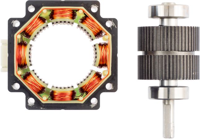 | 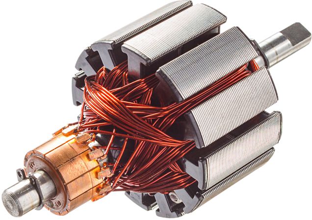 |
| Stepper Motor | BDC Motor |
H-bridge drive circuits are widely used to control of stepper and BDC motors. An H-bridge is built with four switches (solid-state or mechanical). The rotation, stop and reverse of the motor can be realized by controlling the on or off of those tubes. H-bridges are available as integrated circuits, or can be built from discrete components.
") Figure 1 H-Bridge Driver (Left: Clockwise, Center: Stop, Right: Counter-Clockwise)
Figure 1 H-Bridge Driver (Left: Clockwise, Center: Stop, Right: Counter-Clockwise)Across those stepper and BDC related applications, users must accurately control the motor speed, torque or other variables to meet the requirements of actual applications. As a result, the main resources used are as follows:
Hardware
- Microcontroller (MCU): Motor driver controller, which controls analog data acquisition, run control algorithms, monitors the motor status, and communicates with other products
- Predriver: Predriver for power stage
- Power stage: Up to 8× N-type MOSFETs (or IGBTs) in an H-bridge or dual H-bridge configuration
- Analog front end: Collects motor voltage, current, speed, and more
Software
- Application: Task management and scheduling
- Algorithm: Calculate the drive signal output of the motor in real time according to the feedback of the motor and the user input signal
These functions can be realized using TI devices, predrivers, and MOSFETs.
| Motor | MCU | Motor Voltage | Predriver (Device) | Power Stage (Switch Type) |
|---|---|---|---|---|
| Brushed-DC | MSPM0Lxx ARM Cortex M0+ 32 MHz MCUs | 1.65 V to 50 V | H-bridge Motor Driver (DRV82xx series) | |
| 5.5 V to 60 V | H-bridge Gate Driver (DRV870x series) | MOSFET (CSD series) | ||
| 5 V to 115 V | H-bridge Gate Driver (DRV877x series) | |||
| 4.5 V to 70 V | Quad Half-bridge driver (DRV89xx series) | |||
| 5 V to 115 V | Half bridge drivers (UCC2xxx series, LMxxx series) | MOSFET, IGBT | ||
| Stepper | 1.65 V to 70 V | Dual H-Bridge Stepper Driver (DRV84xx series) | ||
| 2 V to 65 V | Dual H-Bridge Intelligent Stepper Driver (DRV88xx series) | |||
Why is MSPM0 considered for stepper and brushed-DC control?
Texas Instruments' scalable M0+ MSPM0Lx mainstream MCUs with on-chip motor control peripherals provides a design for a variety of motor control applications. With up to 32 MHz CPU speed and a portfolio from 8 KB to 64 KB of flash memory with scalable analog integration and motor control peripherals, MSPM0Lxxx devices are an option for stepper and brushed DC motor designs.

- 32-MHz M0+ CPU – Reduces process time for control and sensing signal
- 1-Msps 12-bit ADC module (up to 10 channels) – Sensing H-Bridge current
- Two zero-drift chopper op-amps – Accurately amplifies the 2 H-Bridge current
- High-speed comparators – Enables fast current protection for motor
- Four general-purpose timers – Flexible PWM control and cross triggers
- Synchronization and cross trigger to generate multiphase motor control PWMs
- Up to 8 PWM (can drive four BDC or two stepper motors)
- Robust IO design with glitch filter – Provides a reliable system with motor noise
- Comprehensive communication interfaces – Including UART, I2C, SMBus, SPI, meet all the communication requirements with the motor control system.
- Scalable MCU portfolio with pin-to-pin compatible devices cross wide range of flash memory options.
- Small footprint packages provide options for space constrained designs.
What can MSPM0 do in brushed-DC motor control?
In brushed-DC applications, MSPM0 can monitor the motor status, run algorithms, and generate PWM to drive the motor (through a predriver device). With the help of scalable analog Integration, the MCU can calculate accurate values of bus voltage, motor current, and speed quickly, and then provide input to control algorithm. The MSPM0L13xx can generate eight PWMs and as a result, can drive four BDC motors at the same time.
 Figure 2 MSPM0L13xx Motor Control Block Diagram
for Brushed-DC Control
Figure 2 MSPM0L13xx Motor Control Block Diagram
for Brushed-DC ControlWhat can MSPM0 do in stepper motor control?
In stepper applications, MSPM0 can:
- Monitor the motor status (optional)
- Run BDC or stepper motor control algorithms
- Communicate with a gate driver to set driver or microstepping settings (optional)
- Generate PWM to drive the motor (through a predriver device).
With the help of scalable analog integration, the MCU can calculate accurate values for the bus voltage, motor current, and speed quickly, then provide inputs to the control algorithm. The MSPM0L13xx can generate up to eight PWM signals, and as a result, can drive two stepper motors at the same time.
MSPM0 Stepper Control and Stepper Driver With PWM Interface
Basic stepper drivers often use a PWM interface for stepper control, where specific PWM patterns can provide torque control while controlling the stepper motor's position. To accomplish this, the MSPM0 provides four PWM input signals using a full-step or half-step commutation pattern to control the respective currents through the phases of the stepper motor.
Additionally, many stepper drivers include current regulation from an analog input signal, which can be provided using the 8-bit DAC output of the MSPM0 from an integrated comparator to smooth the current profile. This topology is considered for high torque or low-precision stepper applications such as toys, smart locks, robotics, and security cameras.
 Figure 3 MSPM0L1xxx Stepper Control and Stepper
Driver With PWM Interface
Figure 3 MSPM0L1xxx Stepper Control and Stepper
Driver With PWM InterfaceMSPM0 Stepper Control and Intelligent Stepper Driver With STEP Interface
In higher performance stepper applications that require low noise, precise control, or stall detection, using an intelligent stepper driver capable of up to 1/256 microstepping is preferred. These drivers include indexers and advanced stepper control and protection algorithms and typically only require one PWM signal advance the stepper motor.
Additionally, these drivers can accept an analog input for current regulation and often use a SPI interface to configure the control algorithm, device settings, and diagnose system-level faults. The MSPM0 can interface with intelligent stepper drivers by providing the PWM signals, an 8-bit DAC output voltage for the current regulation, and communicate to the driver using SPI interface. This topology is considered for low-torque and low-noise stepper applications such as printers, ATM machines, stage lighting, office and home automation, medical applications, and 3D printers.
 Figure 4 MSPM0L1xxx Stepper Control and Stepper
Driver With STEP Interface
Figure 4 MSPM0L1xxx Stepper Control and Stepper
Driver With STEP InterfaceDesign details
- Motor control designs in MSPM0-SDK
- MSPM0 Brushed-DC Library
- Supports DRV82xx (motor driver) and DRV87xx (gate driver) devices
- Scalable to discrete driver topologies for high-voltage brushed DC applications
- MSPM0 Stepper Library
- Supports DRV84xx integrated drivers for basic full- and half-stepping control
- Supports DRV88xx intelligent drivers for up to 1/256 microstepping
- MSPM0 Brushed-DC Library
Peripheral features
- Timer – Generates PWM and detects Hall sensor feedback
- Generate PWM (TIMG)
- Configures the cross trigger between TIMG instances to generate up to eight PWMs
- Detect Hall sensor feedback (optional)
Use capture and compare (CC) inputs to XOR digital hall signals and creates frequency generator (FG) pulses for speed computation
- Generate PWM (TIMG)
- ADC – Sensing current and voltage
- Enables the 1-Msps ADC with multiple channels to sense motor current and bus voltage
- SPI – Communicates with the gate driver for the stepper motor (optional)
- Communicates with the gate driver to set subdivision parameters
- OPA – Standard (STD) mode
- 6-MHz GBW in standard (STD) mode
- 4-V/µs slew rate in STD mode
- 6-µV/°C input offset voltage temperature drift in STD mode
-
 Figure 5 MSPM0L13xx OPA Block Diagram
for Current Sensing
Figure 5 MSPM0L13xx OPA Block Diagram
for Current Sensing - COMP – High-speed mode
- The 8-bit DAC in COMP sets the current limit threshold, and COMP generates an interrupt to the CPU if the current is over the threshold.
- The CPU stops the PWM at this interrupt.
- DAC settling time: 1 µs in static mode
- COMP response time: 40 ns in high-speed mode
- Timer – Generates PWM and detects Hall sensor feedback
 Figure 6 MSPM0L13xx COMP Block Diagram for
Current Protection
Figure 6 MSPM0L13xx COMP Block Diagram for
Current ProtectionResources
Order a MSPM0 LaunchPad development kit and DRV8xxx EVM today to start evaluating MSPM0 for a motor control system. Jump-start a motor control design with MSPM0 code examples and interactive online trainings.
- MSPM0-SDK
- MSPM0 overview page
- MSPM0 LaunchPad development kit
- MSPM0 Academy
- DRV8xxx EVM
- DRV8706S-Q1EVM (Brushed-DC Control)
- DRV8411AEVM (Basic Stepper Control)
- DRV8889-Q1EVM (Intelligent Stepper Control)
- TI Precision Labs - Motor Drivers: Stepper Motor Driver Basics
- TI Precision Labs - Motor Drivers: Brushed-DC Basics
- TI Precision Labs - Motor Drivers: The H-Bridge