SLAU278AH May 2009 – March 2021
- 1Read This First
-
1Get Started Now!
- 1.1 Kit Contents, MSP-TS430xx
- 1.2 Kit Contents, MSP-FET430xx
- 1.3 Kit Contents, MSP-FET
- 1.4 Kit Contents, MSP-FET430UIF
- 1.5 Kit Contents, MSP-FET430PIF
- 1.6 Kit Contents, eZ430-F2013
- 1.7 Kit Contents, eZ430-T2012
- 1.8 Kit Contents, eZ430-RF2500
- 1.9 Kit Contents, eZ430-RF2500T
- 1.10 Kit Contents, eZ430-RF2500-SEH
- 1.11 Kit Contents, eZ430-Chronos-xxx
- 1.12 Kit Contents, FET430F6137RF900
- 1.13 Kit Contents, EM430Fx1x7RF900
- 1.14 Hardware Installation, MSP-FET and MSP-FET430UIF
- 1.15 Hardware Installation, MSP-TS430xxx, MSP-FET430Uxx, FET430F6137RF900, EM430Fx1x7RF900
- 1.16 Hardware Installation, eZ430-XXXX, MSP-EXP430G2, MSP-EXP430FR5739, MSPEXP430F5529
- 1.17 Important MSP430 Documents on the Web
-
2Design Considerations for In-Circuit Programming
- 2.1 Signal Connections for In-System Programming and Debugging
- 2.2 External Power
- 2.3
Bootloader (BSL)
-
A Frequently Asked Questions and Known Issues
- A.1 Hardware FAQs
-
A.2 Known Issues
- MSP-FET430UIF
-
MSP-FET430PIF
-
B Hardware
- B.1 MSP-TS430D8
- B.2 MSP-TS430PW14
- B.3 MSP-TS430L092
- B.4 MSP-TS430L092 Active Cable
- B.5 MSP-TS430PW20
- B.6 MSP-TS430RHL20
- B.7 MSP-TS430PW24
- B.8 MSP-TS430RGE24A
- B.9 MSP-TS430DW28
- B.10 MSP-TS430PW28
- B.11 MSP-TS430PW28A
- B.12 MSP-TS430RHB32A
- B.13 MSP-TS430DA38
- B.14 MSP-TS430QFN23x0
- B.15 MSP-TS430RSB40
- B.16 MSP-TS430RHA40A
- B.17 MSP-TS430DL48
- B.18 MSP-TS430PT48
- B.19 MSP-TS430PT48A
- B.20 MSP-TS430RGZ48B
- B.21 MSP-TS430RGZ48C
- B.22 MSP-TS430PM64
- B.23 MSP-TS430PM64A
- B.24 MSP-TS430PM64D
- B.25 MSP-TS430PM64F
- B.26 MSP-TS430RGC64B
- B.27 MSP-TS430RGC64C
- B.28 MSP-TS430RGC64USB
- B.29 MSP-TS430PN80
- B.30 MSP-TS430PN80A
- B.31 MSP-TS430PN80B
- B.32 MSP-TS430PN80C
- B.33 MSP-TS430PN80USB
- B.34 MSP-TS430PZ100
- B.35 MSP-TS430PZ100A
- B.36 MSP-TS430PZ100B
- B.37 MSP-TS430PZ100C
- B.38 MSP-TS430PZ100D
- B.39 MSP-TS430PZ100E
- B.40 MSP-TS430PZ5x100
- B.41 MSP-TS430PZ100USB
- B.42 MSP-TS430PZ100AUSB
- B.43 MSP-TS430PEU128
- B.44 EM430F5137RF900
- B.45 EM430F6137RF900
- B.46 EM430F6147RF900
-
B Hardware
-
A Frequently Asked Questions and Known Issues
B.21 MSP-TS430RGZ48C
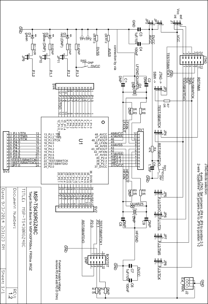
 Figure 4-42 MSP-TS430RGZ48C Target Socket Module, Schematic
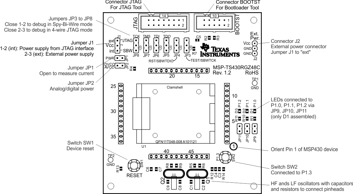
 Figure 4-43 MSP-TS430RGZ48C Target Socket Module, PCB
Note:
LFOSC and HFOSC pins are swapped at SV1.
42_HFXIN (pin 42) → SV1 (pin 7)
43_HFXOUT (pin 43) → SV1 (pin 6)
45_LFXIN (pin 45) → SV1 (pin 10)
46_LFXOUT (pin 46) → SV1 (pin 9)
Table 4-22 MSP-TS430RGZ48C Bill of Materials
| Pos | Ref Des | Number Per Board | Description | Digi-Key Part Number | Comment |
|---|---|---|---|---|---|
| 1 | SV1, SV2, SV3, SV4 | 4 | 12-pin header, TH | DNP: headers and receptacles enclosed with kit. Keep vias free of solder. | |
| SAM1029-12-ND | : Header | ||||
| : Receptacle | |||||
| 1.1 | SV1, SV2, SV3, SV4 | 4 | 12-pin receptable, TH | DNP: headers and receptacles enclosed with kit. Keep vias free of solder. | |
| : Header | |||||
| SAM1213-12-ND | : Receptacle | ||||
| 2 | JP1, JP2, JP9 | 3 | 2-pin header, male, TH | SAM1035-02-ND | Place jumper on header |
| 3 | JP10, JP11 | 2 | 2-pin header, male, TH | SAM1035-02-ND | DNP |
| 4 | J1, JP3, JP4, JP5, JP6, JP7, JP8 | 7 | 3-pin header, male, TH | SAM1035-03-ND | Place jumpers on pins 2-3 |
| 5 | J2 | 1 | 3-pin header, male, TH | SAM1035-03-ND | |
| 6 | JP1, JP2, JP9, J1, JP3, JP4, JP5, JP6, JP7, JP8 | 10 | Jumper | 15-38-1024-ND | Place on: JP1, JP2, JP9, J1, JP3, JP4, JP5, JP6, JP7, JP8 |
| 7 | R2, R3, R5, R6, R8, R9, R10, R11, R14 | 9 | DNP, 0805 | DNP | |
| 8 | R12, R13, R7 | 3 | 0R, 0805 | 541-000ATR-ND | |
| 9 | C5 | 1 | 1.1nF, CSMD0805 | 490-1623-2-ND | |
| 10 | C3, C7 | 2 | 1uF, 10V, CSMD0805 | 490-1702-2-ND | |
| 11 | R4 | 1 | 47k, 0805 | 541-47000ATR-ND | |
| 12 | C4, C6 | 2 | 100nF, CSMD0805 | 311-1245-2-ND | |
| 13 | R1 | 1 | 330R, 0805 | 541-330ATR-ND | |
| 14 | C1, C2, C8, C9 | 4 | DNP, CSMD0805 | DNP | |
| 15 | SW1, SW2 | 2 | EVQ-11L05R | P8079STB-ND | DNP |
| 16 | BOOTST | 1 | 10-pin connector, male, TH | HRP10H-ND | DNP, keep vias free of solder |
| 17 | JTAG | 1 | 14-pin connector, male, TH | HRP14H-ND | |
| 18 | Q1 | 1 | DNP: MS3V-TR1 (32768kHz, 20ppm, 12.5pF) | depends on application | Micro Crystal, DNP, enclosed in kit, keep vias free of solder |
| 19 | Q2 | 1 | DNP, Christal | depends on application | DNP, keep vias free of solder |
| 20 | U1 | 1 | Socket: QFN11T048-008 A101121-001 | Manuf.: Yamaichi | |
| 20.1 | U1 | 1 | MSP430FR5969IRGZ | DNP: enclosed with kit. Is supplied by TI. | |
| 21 | D1 | 1 | green LED, DIODE0805 | P516TR-ND | |
| 22 | D3 | 1 | red (DNP), DIODE0805 | DNP | |
| 23 | D2 | 1 | yellow (DNP), DIODE0805 | DNP | |
| 24 | TP1, TP2 | 2 | Testpoint | DNP, keep pads free of solder | |
| 25 | Rubber stand off | 4 | Buerklin: 20H1724 | apply to corners at bottom side | |
| 26 | PCB | 1 | 79.6 x 91.0 mm | MSP-TS430RGZ48C Rev. 1.2 | 2 layers, black solder mask |