SLLA272D February 2008 – May 2021
10 Minimum Node Spacing
The RS-485 bus is a distributed parameter circuit whose electrical characteristics are primarily defined by the distributed inductance and capacitance along the physical media, which includes the interconnecting cables and printed-circuit board traces.
Adding capacitance to the bus in the form of devices and their interconnections lowers the bus impedance and causes impedance mismatches between the media and the loaded section of the bus. Input signals arriving at these mismatches are partially reflected back to the signal source distorting the driver output signal.
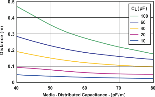
Ensuring a valid receiver input voltage level during the first signal transition from an output driver anywhere on the bus requires a minimum loaded bus impedance of Z′ > 0.4 x Z0, which can be achieved by keeping the minimum distance, d, between bus nodes:

Where CL is the lumped load capacitance and C, the media capacitance (cable or PCB trace) per unit length.
 Figure 10-1 Minimum Node Spacing With Device and
Media Capacitance
Figure 10-1 Minimum Node Spacing With Device and
Media CapacitanceEquation 4 presents the relationship for the minimum device spacing as a function of the distributed media and lumped-load capacitance; Figure 10-1 shows this relationship graphically.
Load capacitance includes contributions from the line circuit bus pins, connector contacts, printed-circuit board traces, protection devices, and any other physical connections to the trunk line as long as the distance from the bus to the transceiver (the stub) is electrically short.
Putting some values to the individual capacitance contributions:
-
5-V transceivers typically possess a capacitance of 7 pF, whereas 3-V transceivers have approximately twice that capacitance at 16 pF. Board traces add approximately 0.5 to 0.8 pF/cm depending on their construction. Connector and suppression device capacitance can vary widely. Media distributed capacitance ranges from 40 pF/m for low capacitance, unshielded, twisted-pair cable to 70 pF/m for backplanes.