SLLA486A May 2020 – May 2021 ISO1042 , ISO1042-Q1 , ISO1044 , ISO1050 , ISOW1044
- Trademarks
- 1 When Do I Need to Isolate CAN?
- 2 What are the Options Available to Isolate CAN Bus?
- 3 Now That I Have Isolated CAN Signal Path, How Do I Generate Isolated Power?
- 4 What’s the Reason Behind Terminating the Bus, Do I Need it, and How to Achieve it?
- 5 What’s the Difference Between Common Mode Range and Bus Standoff Mentioned in Data Sheet?
- 6 Now That I Have Taken Care of the Termination Resistor, What Other Components do I Need on the Bus Side?
- 7 When Connecting Isolated CAN Nodes in a Network, What Should be Done with the Floating Bus-Side Ground Connection?
- 8 Is There a Limitation on Minimum Data Rate That I Can Operate? What About the Maximum Data Rate Achievable in a Network?
- 9 Is There a Limit on Maximum Number of Nodes That I Can Connect in CAN Network?
- 10What Factors Decide the Maximum Communication Distance in a CAN Network?
- 11What is the Maximum Value of Bus Capacitance That Can be Introduced Between CANH to GND and CANL to GND? Can Higher Capacitance Damage the Device?
- 12Is There a Way to Extend the Maximum Communication Distance?
- 13What is Stub Length? What are the Design Considerations Around it?
- 14I am Seeing Larger Differential CAN Voltage for Some Bits of CAN Packet Compared to Rest of the Packet When I am Communicating in a Network with Multiple Nodes Connected. Why?
- 15References
- 16Revision History
3 Now That I Have Isolated CAN Signal Path, How Do I Generate Isolated Power?
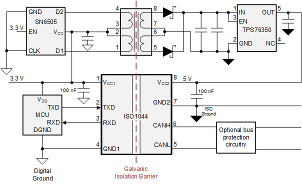
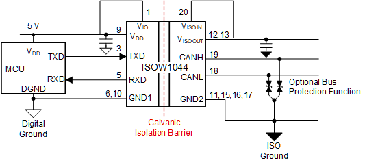
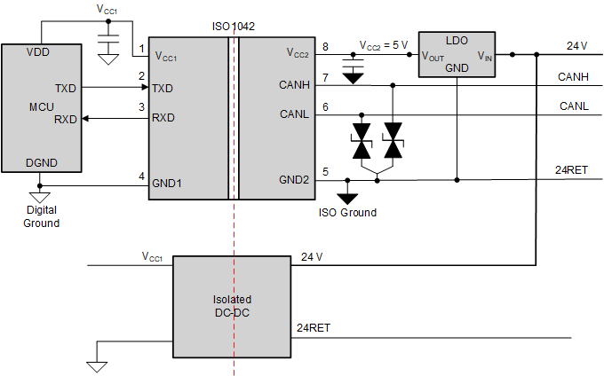
Multiple options are available for isolated power generation for a CAN node. If the field side (for example, bus side) circuitry needs more power than just powering the CAN transceiver, push-pull transformer drivers like TI’s SN6505B driving an external transformer is a simple-to-use and low cost solution as shown in Figure 3-1. For space-constrained applications the ISOW1044 provides signal isolation, DC/DC converter, and a CAN FD transceiver in a single chip to reduce solution size and simplify the design process, as shown in Figure 3-2. Sometimes in certain industrial applications, such as DeviceNet, a 24-V supply is available on the field side which can be used as shown in Figure 3-3. To learn more on this topic, read the application brief, How to Isolate Signal and Power in Isolated CAN Systems
 Figure 3-1 Isolated Power Generation Using Push-Pull
Topology
 Figure 3-2 Isolated Signal and Power Using Small
Form-Factor ISOW1044
 Figure 3-3 DeviceNet Application Schematic