SLLA498 October 2020
5.2 Highly Efficient and Reliable Inverter Concept (HERIC)
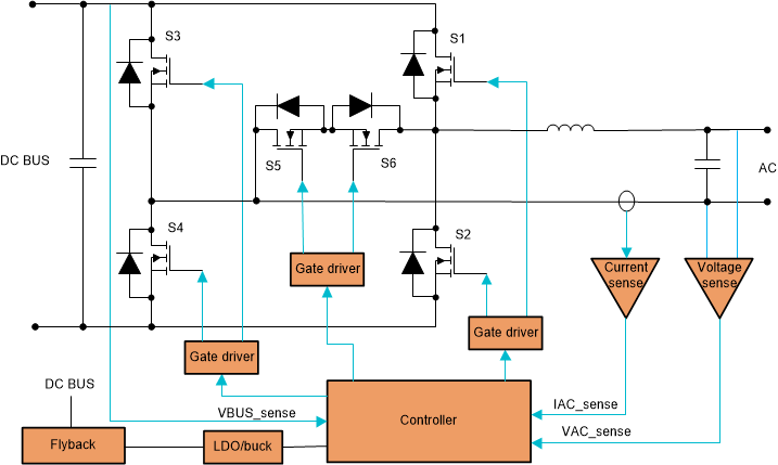
The HERIC inverter is an improvement over the two level H-bridge topology by adding two more switches as Figure 5-2.
 Figure 5-2 HERIC Converter.
 The converter operates as follows: During the positive half-cycle of the grid voltage S5 is kept ON, S1 and S4 are switched simultaneously at the switching frequency, supplying a positive voltage to the load, while S2, S3 and S6 are OFF. During this time (positive active vector) current flows from the DC input to the grid. When zero vector (freewheeling period) occurs, S1 and S4 also are switched OFF and the current flows through S5 and anti-parallel diode of S6. During the negative half-cycle of the grid voltage, S6 is kept ON, while S2 and S3 are switched together at the switching frequency, while S1, S4 and S5 are OFF. During this period (negative active vector) the current flows from the DC input to the grid in opposite direction. When zero vector (freewheeling period) occurs, S2 and S3 also turn OFF, and current freewheels through S6 and anti-parallel diode of S5. As can be seen from this operation, the body diodes of S1 to S4 do not come into operation at all and hence we can use Si MOSFETs for these and switch them at relatively higher frequency. Since the switches S5 and S6 are switching only at line frequency, we can use IGBTs (their anti-parallel diodes need to be ultra-fast though).
Since we are able to achieve three level switching (positive vector, zero vector and negative vector) low distortion can be achieved on the output. The TNPC inverter is an extension of the HERIC topology. This DC/AC topology being bidirectional, is an option to consider for the bidirectional DC/AC stage (see Figure 3-1) between the HV DC Bus and the AC Bus in a storage ready solar inverters.