SLLA579 January 2022 ISOUSB211
- Trademarks
- 1PCB Trace Insertion Loss and Inter-Symbol Interference
- 2Transmitter Pre-Emphasis and Receiver Equalizer
- 3Selecting an Optimal Pre-emphasis for Your System
- 4Eye-Diagrams for 6 inch to 4 feet Traces with all Nine Pre-Emphasis Settings for USB 2.0 Near-end Eye-mask
- 5Eye-Diagrams for 6 inch to 4 feet Traces and 5m Cable with all Nine Pre-emphasis Settings for USB 2.0 Far-end Eye-mask
- 6Using Receiver Equalizer and Transmitter Pre-emphasis for Channel Loss Compensation Simultaneously
- 7Summary
1 PCB Trace Insertion Loss and Inter-Symbol Interference
A redriver and an isolated repeater are devices that enhance the signal integrity by equalizing and amplifying the signals. The main difference is the redriver behaves as an analog buffer which its output waveform is linearly proportional to the input waveform without equalization applied, but the isolated repeater consists of a digital isolator that generates a fresh copy of the signal across the isolation barrier based on the logic of the input signal. The input jitter that has not been compensated by the equalizer of the redriver and isolated repeater will be reflected at the transmitter output. Since the isolated repeater has an additional On-Off Keying circuitry, the total output jitter of an isolated repeater is the root sum squared of the jitter generated by the isolation circuitry and the uncompensated input jitter.
Figure 1-2 shows a printed circuit board (PCB) that consists of five pairs of differential traces. The USB 2.0 type-A to type-B receptacles placed at the two ends of these traces connect these traces to the ISOUSB211DPEVM through USB cables. The differential impedance (ZDiff) of these differential traces was designed to be 90-ohm achieved by setting the track-width to be 50mil, track-spacing to be 9 mil, track-height to be 0.4 mil, isolation height to be 59.2 mil, and the dielectric constant to be 4.9. Figure 1-3 shows the USB receptacles have been replaced by SubMiniature version A (SMA) connectors to properly connect to a vector network analyzer (VNA) for measuring the insertion loss of these differential traces.
Figure 1-4 shows the measured differential insertion losses for the five differential traces ranging from 6 inches to 4 feet. The first observation is a longer trace length results in a higher DC loss. The second observation is the insertion loss of a PCB trace increases proportionally to the transmission frequency. The third observation is the ringing on the curves caused by the impedance discontinuity along the traces. In general, the DC loss causes signal amplitude reduction similar to the effect of a resistor. The insertion loss at high frequency (operating frequency) and the reflection cause inter-symbol interference (ISI), thereby greatly reducing the receiver’s drive length and increasing bit-error rate (BER).
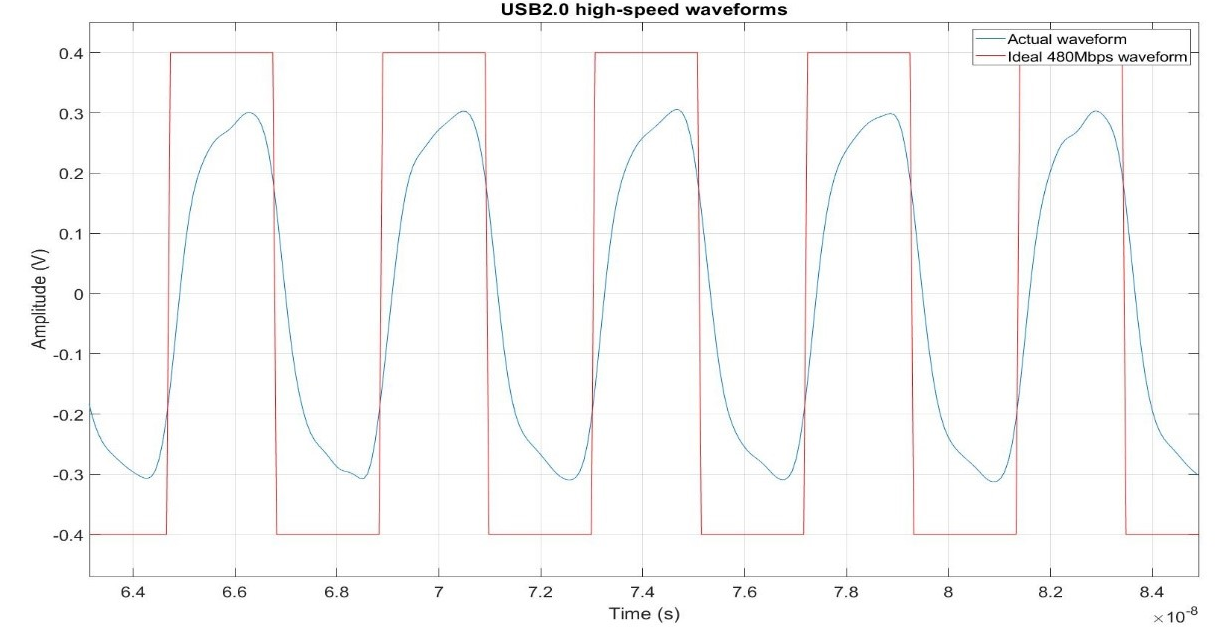
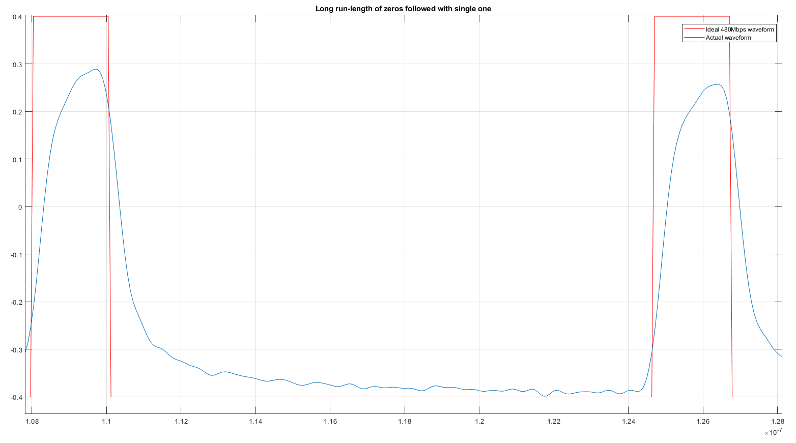
A signal traveling through an ideal transmission medium such as a superconductor completes the transition within a symbol interval as shown in Figure 1-5. However, when the signal travels through the aforementioned lossy backplane, the transition expands to adjacent intervals. The resulting effect is the signal compels to make a transition to the opposite rail even before completing its transition when transmitting a high activity factor data such as a clock pattern and this behavior is called an ISI. Figure 1-6 shows the worst-case happens when there is a long run-length of zeros followed by a single one or vice versa in which the signal has sufficient time to reach one of the rails, but this causes the next opposite transition to have lowest peak voltage and directly reduces the eye-height. Figure 1-7 shows the impact of the ISI in eye diagrams for FR4 traces from 6inch, 1-feet, 2-feet, 3-feet, to 4-feet. The eye height and eye width shrink proportionally to the insertion loss of the lossy FR-4 traces.
 Figure 1-5 Ideal and Actual USB 2.0
Waveforms
 Figure 1-6 Ideal and Actual USB 2.0
Waveforms with Long Run-length
 Figure 1-7 Eye-diagrams for 6 inch to 4
feet Traces