SLLU091A January 2006 – September 2022 ISO721 , ISO721M
4 EVM Signal Paths of the ISO721 and ISO721M Isolators
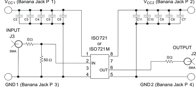
This multifunctional EVM is designed with signal paths shown in Figure 4-1 for the analysis of the ISO721 and ISO721M, as well as future isolator configurations.
 Figure 4-1 The ISO721 and ISO721M EVM Schematic
Table 4-1 EVM Connections
| Connection | Label | Description |
|---|---|---|
| J1 | SMA connector (unused) | |
| J2 | SMA connector to the output pin 6 | |
| J3 | SMA connector to the input pin 2 | |
| J4 | SMA connector (unused) | |
| P1 | VCC1 | Input power supply banana jack |
| P2 | VCC2 | Output power supply banana jack |
| P3 | GND1 | Input power ground connection banana jack |
| P4 | GND2 | Output power ground connection banana jack |
| JMP1 | 3-pin jumper (unused) | |
| JMP2 | 3-pin jumper (unused) | |
| JMP3 | 3-pin jumper – VCC1, input, GND1 | |
| JMP4 | 3-pin jumper (unused) |