SLOA212A December 2014 – February 2016 RF430FRL152H
3 Demonstration With TRF7970AEVM
The demonstration board can be exercised with the use of the TRF7970AEVM and the RF430FRL152H GUI. The software and complete details are available in the RF430FRL152HEVM User's Guide (SLAU607).
Step-by-step instructions for use with this specific reference design are listed below:
- Install the RF430FRL152H GUI and drivers as shown in the Installation of the Software and Drivers section of the RF430FRL152HEVM User's Guide (SLAU607).
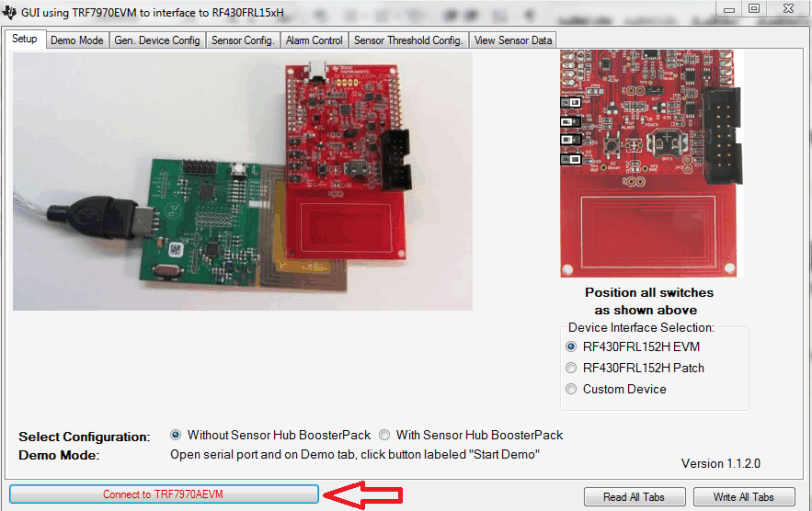
- Plug in the TRF7970AEVM, open the RF430FRL152H GUI, and click “Connect to TRF7970AEVM” (as shown in Figure 3).
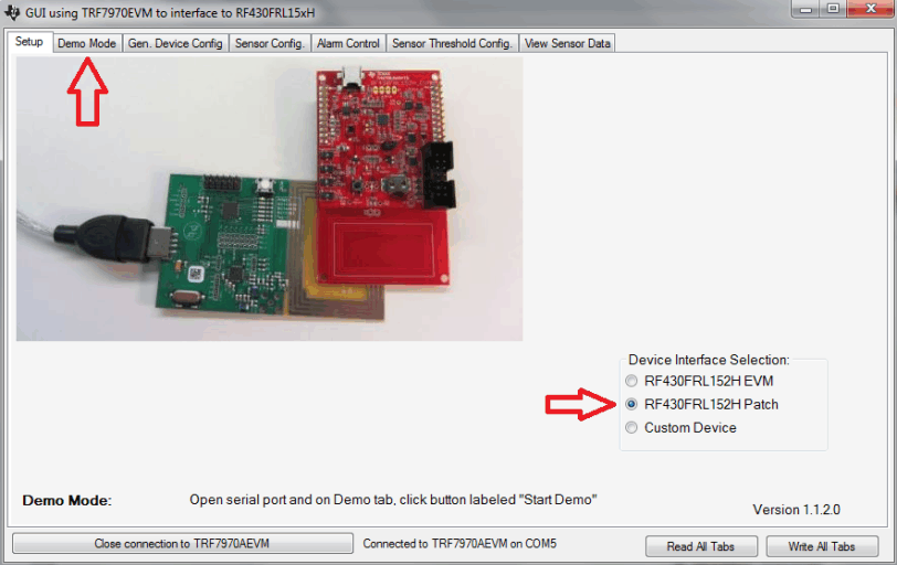
- Select the “RF430FRL152H Patch” and then click the “Demo Mode” tab (as shown in Figure 4).
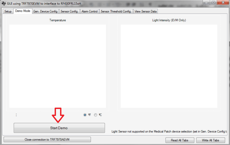
- Align the Patch Board in parallel with the TRF7970AEVM antenna and then click “Start Demo” (as shown in Figure 5. First, this writes the configuration for the ADC and frequency of measurements to the RF430FRL152H. Then, it begins reading the subsequent sensor measurements as they are updated.
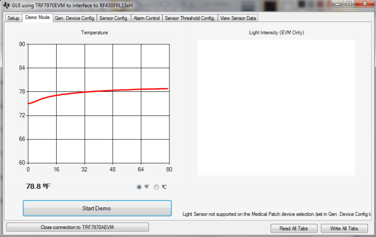
- As long as the patch board stays within range of the TRF7970AEVM antenna, the measurements will continue to be taken and plotted on the graph (as shown in Figure 6). The latest measurement is shown as a numeric value, 78.8°F, in Figure 6. The GUI also provides the option to display in Fahrenheit or Celsius.
 Figure 3. Connect to TRF7970AEVM
  Figure 4. Select RF430FRL152H Patch
  Figure 5. Start Demo
  Figure 6. Temperature Measurements