SLVAE30E February 2021 – March 2021 TPS1H000-Q1 , TPS1H100-Q1 , TPS1H200A-Q1 , TPS1HA08-Q1 , TPS25200-Q1 , TPS27S100 , TPS2H000-Q1 , TPS2H160-Q1 , TPS2HB16-Q1 , TPS2HB35-Q1 , TPS2HB50-Q1 , TPS4H000-Q1 , TPS4H160-Q1
- Trademarks
- 1Introduction
- 2Driving Resistive Loads
- 3Driving Capacitive Loads
- 4Driving Inductive Loads
- 5Driving LED Loads
- 6Appendix
- 7References
- 8Revision History
2.2 Application Example
A common resistive load in a vehicle is a seat heater. A long coil is placed inside the seat and it heats up when current flows through it. The current is controlled so that the correct amount of heat is produced. A reference design of this application can be found at: Smart Power Switch for Seat Heater Reference Design.
 Figure 2-1 Seat Heater Resistive Load Application
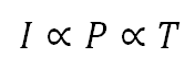
In a seat heating application there needs to be discrete temperature steps in the temperature setting of the seat. All vehicles with this feature allow the user to select the correct temperature range that suits them. It can be inferred that the temperature correlates directly with the current flowing through the load and therefore to adjust the temperature the current must be varied proportionally.
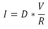
To do this a microcontroller that is controlling the high side switch pulse width modulates (PWM's) the enable pin. This turns the device on and off at a fast rate that gives an effective current which can be calculated in Equation 3 based on the duty cycle D. When PWMing the enable pin there is an associated power loss that comes with turning the device on and off. This switching loss and other power calculations are explained in Section 2.4.2.
The microcontroller also needs to be measuring the current going through the high side switch in order to know what the temperature currently is in the seat. This means that the current sensing output of the high side switch needs to be accurate so that the exact temperature is known. This accurate current sensing will be discussed in Section 2.3.1.
This is an example of a seat heater load but in reality there are many different resistive loads such as incandescent lamps and industrial heaters. Each of these loads will require a different current level and therefore the short circuit protection level will also be varied. This protection level needs to be high enough to let the nominal current pass through but low enough that it does not cause damage to the system itself.