SLVAE30E February 2021 – March 2021 TPS1H000-Q1 , TPS1H100-Q1 , TPS1H200A-Q1 , TPS1HA08-Q1 , TPS25200-Q1 , TPS27S100 , TPS2H000-Q1 , TPS2H160-Q1 , TPS2HB16-Q1 , TPS2HB35-Q1 , TPS2HB50-Q1 , TPS4H000-Q1 , TPS4H160-Q1
- Trademarks
- 1Introduction
- 2Driving Resistive Loads
- 3Driving Capacitive Loads
- 4Driving Inductive Loads
- 5Driving LED Loads
- 6Appendix
- 7References
- 8Revision History
4.5 Turn-Off Phase
Inductive loads seek to maintain continuous current flow in one direction. When an inductive load is turned off, the inductive load reverses the polarity of the applied voltage to prevent the immediate loss of current flow. That means if the voltage across the inductive load is positive during the on-phase, it will become negative when applied power is removed.
Immediately before the switch is opened, the load current I0 is equal to ILOAD,DC as calculated in Equation 31. Immediately after the switch opens the inductor current will begin decaying from I0 to zero as a continuous function. With a negative dI/dT and no applied VBAT, the voltage across the inductive load will invert and a negative voltage will appear on the high side switch output. This process is shown in Figure 4-3
 Figure 4-3 Inductive Load Turn-Off Phase
Applying Kirchhoff’s voltage law gives Equation 33.
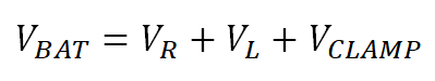
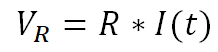
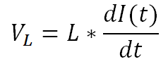
Where VL is the voltage across the inductive element of the load, VR is the voltage across resistive element of the load, VCLAMP is the voltage across the switch FET VDS during a transient voltage spike, and VBAT is the supply voltage. Ohm’s law for resistors and inductors are seen in Equation 34 and Equation 35:
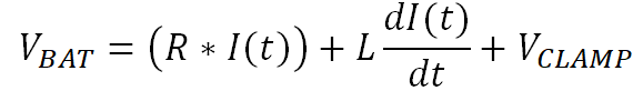
Inserting those into Equation 33 gives Equation 36:
Rearranging Equation 36 gives Equation 37, which is a first order differential equation for the load current.
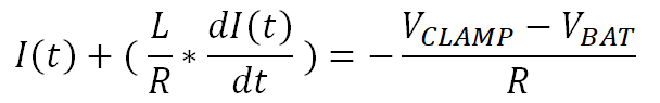
This is solved in Equation 38.
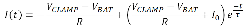
Where I0 is the current when the switch is initially opened. Equation 38 shows that the current decays exponentially with negative slope and time constant τ = L/R. This equation serves as the basis for calculating the inductive load demagnetization energy. The current has two components: on the left side of the equation is the steady state current contribution and on the right is the transient current contribution that is modified by the exponential time factor. The load is demagnetized completely when the total current is zero and the two components are equal.
Note that Equation 38 is valid only from time t = 0 until the load is completely demagnetized. This demagnetization time is calculated in the next section.