SLVAE30E February 2021 – March 2021 TPS1H000-Q1 , TPS1H100-Q1 , TPS1H200A-Q1 , TPS1HA08-Q1 , TPS25200-Q1 , TPS27S100 , TPS2H000-Q1 , TPS2H160-Q1 , TPS2HB16-Q1 , TPS2HB35-Q1 , TPS2HB50-Q1 , TPS4H000-Q1 , TPS4H160-Q1
- Trademarks
- 1Introduction
- 2Driving Resistive Loads
- 3Driving Capacitive Loads
- 4Driving Inductive Loads
- 5Driving LED Loads
- 6Appendix
- 7References
- 8Revision History
4.5.3 Total Energy Dissipated During Demagnetization
During the switch off time, the demagnetization energy must be dissipated in the high side switch. In the absence of proper demagnetization the FET can be severely damaged and also can cause damage elsewhere in the system.
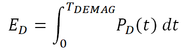
Selection of a high side switch can be determined once the demagnetization energy is well defined. The dissipated energy ED is calculated in Equation 45 by integrating the instantaneous power losses PD(t) over the demagnetization time TDEMAG.
Taking Equation 45 and Equation 44 together and solving the integration gives Equation 48.

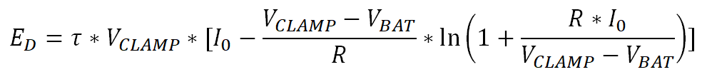
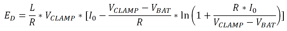
Equation 48 allows us to calculate the inductive demagnetization energy during switch off.
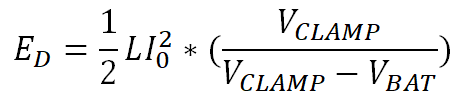
In typical automotive and industrial applications where the nominal supply voltage VBAT are 12 V and 24 V respectively, the term in the natural logarithm is always less than one because the maximum R × I0 value is equal to VBAT, while VCLAMP will always be higher, with a typical nominal value of 60 V. This allows us to simplify Equation 48 into Equation 49.
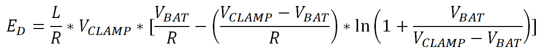
The logarithmic term in Equation 49 can be converted to a polynomial by using the Taylor series in Equation 50.
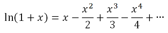
This polynomial function has infinite terms but converges when x is less than 1. In industrial applications where VBAT = 24 V and VCLAMP = 60 V, Equation 51 calculates the values of the first few terms.
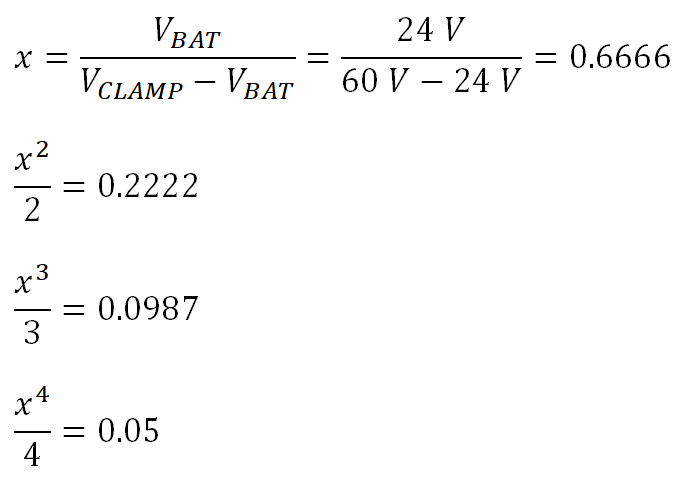
The signs of the terms in the Taylor series are alternating and decreasing. With estimation of less than 5% error, all terms after the second can be eliminated and Equation 49 can be simplified to Equation 54.

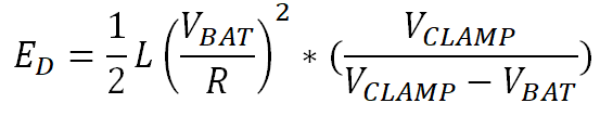
Equation 54 allows a designer to calculate the total demagnetization energy that must be dissipated with the high side switch during an inductive turn off event. This can be compared to the Smart High Side Switch demagnetization capabilities to determine if the device can dissipate the energy alone or if an external clamp must be used to safely demagnetize the inductive load.