SLVAE30E February 2021 – March 2021 TPS1H000-Q1 , TPS1H100-Q1 , TPS1H200A-Q1 , TPS1HA08-Q1 , TPS25200-Q1 , TPS27S100 , TPS2H000-Q1 , TPS2H160-Q1 , TPS2HB16-Q1 , TPS2HB35-Q1 , TPS2HB50-Q1 , TPS4H000-Q1 , TPS4H160-Q1
- Trademarks
- 1Introduction
- 2Driving Resistive Loads
- 3Driving Capacitive Loads
- 4Driving Inductive Loads
- 5Driving LED Loads
- 6Appendix
- 7References
- 8Revision History
4.5.6 Calculations
The detailed calculation is shown for Load 1, Load 2 and Load 3 can also be calculated following the same steps.
The following steps allow us to calculate the demagnetization energy of the load:
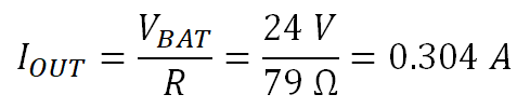
- Determine the supply voltage VBAT, which is 24 V
- Calculate the worst case steady state load current. For Load 1, the worst case
load current is at –40⁰C, giving R = 79 Ω. The steady state current is
calculated as Equation 55.
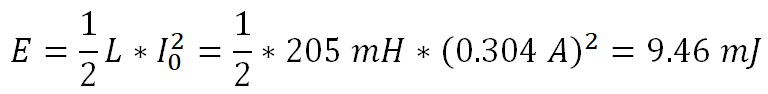
- Calculate the stored energy during the on time from the inductance value:
Equation 56.
- Calculate the demagnetization time: Equation 57.This means with the internal clamp at 60 V the stored energy will demagnetize in 1.32 ms

- Calculate the demagnetization energy: Equation 58.

Load 1 has a current of 0.304 A, inductance of 205 mH and a stored magnetic energy of 9.46 mJ. The stored magnetic energy will be demagnetized over the high side switch with a total demagnetization energy that must be absorbed of 15.67mJ. Lets look to see if the TI Smart High Side Switch TPS4H160-Q1 can dissipate this energy.
The TPS4H160-Q1 is a quad channel high side switch that is widely used for driving inductive loads in both industrial and automotive systems. Like all TI Smart High Side Switches, the TPS4H160-Q1 includes an integrated inductive clamp that allows it demagnetize inductive loads without external circuitry. To determine whether this device can handle this inductive load, reference the device’s demagnetization capability plot which shows the maximum load current or total energy for a given inductance. Demagnetization capability plots are available in Appendix B. The plot for the TPS4H160-Q1 is shown in Figure 4-5:
 Figure 4-5 TPS4H160-Q1 Demagnetization
Capability
Figure 4-5 TPS4H160-Q1 Demagnetization
CapabilityTo determine capability for the 205 mH described in Load 1, find 205 mH on the horizontal axis. Figure 4-5 shows that at 205 mH, the TPS4H160-Q1 can demagnetize 0.75 A and dissipate 90 mJ. The load calculations above gave a load current of 0.304 A and a dissipation of 15.76 mJ, so the TPS4H160-Q1 can safely demagnetize this load with significant margin.
Repeating these calculations for Load 2, which has 50 Ω resistance 48.4 mH inductance, we see a steady state current of 0.48 A and a calculated demagnetization energy of 9.29 mJ. Using Figure 4-5, we see that for 48.4 mH, TPS4H160-Q1 can demagnetize a maximum of 1.1 A and dissipate up to 55 mJ. Similar to Load 1, the device can comfortable demagnetize Load 2.
Looking at Load 3, we see that it has 7.5 Ω resistance and an inductance of 35 mH. This allows us to calculate the steady state current at 3.2 A and the demagnetization energy at 298.6 mJ. Looking at Figure 4-5, we see that for a 35 mH inductive load, the TPS4H160-Q1 can drive a maximum of 1.5 A and dissipate 50 mJ. This is lower than the calculated requirements, so the TPS4H160-Q1 cannot drive this load without an external TVS diode to clamp the inductive energy.
Note that even though the inductance for Load 3 is much lower than that of Load 1, the higher Load 3 current significantly increases the demagnetization energy that must be dissipated. This highlights the importance of knowing both the inductance and load current rather than just one or the other.