SLVAE36A September 2018 – July 2021 LM43600 , LM43601 , LM46001 , LM46002 , LM5160A , LM5161 , LM5165 , LM5166 , LM61460-Q1 , LM73605 , LM73605-Q1 , LM73606-Q1 , LM76003 , LMR33620 , LMR33630 , LMR36006 , LMR36015 , LMR36500 , LMR36501 , LMR36502 , LMR36503 , LMR36506 , LMZ36002 , LMZM23600 , LMZM23601 , LMZM33602 , LMZM33603 , LMZM33606 , TPS54218 , TPS54360B , TPS54418 , TPS54424 , TPS54560B , TPS54618 , TPS55010 , TPS62148 , TPS62821 , TPS62822 , TPS62823 , TPS82130 , TPS82140 , TPS82150 , TPSM365R15 , TPSM365R3 , TPSM365R6
4 Isolation Improving Electrical Noise Immunity
PLCs use data transmission systems, such as RS485, but other communication protocols may be employed, such as Profibus, Profinet, or Ethernet. The remotely located nodes of a communication network usually draw their supply from different points in the electrical installation system. A remotely located power source can experience large ground potential differences due to multiple, non-standardized grounding techniques, which cause multiple ground paths and loops. A ground loop is created when providing a direct connection from a ground wire between the transmitter ground and a remote receiver ground. Ground loop currents can be extremely high, because they connect different ground potentials via low-impedance wiring. As a result, high loop currents induce voltages into transmission signal wires causing signal distortion and data errors. Breaking ground loops through galvanic isolation not only prevents loop currents, but is the most reliable method to solve high ground potential differences. Galvanic isolation allows the input, which is referenced to the ground from the input side, to be independent from the ground at the output side, which significantly enhances the common mode rejection and improves noise performance. It is important to have an area on the circuit board that is “isolated” from potentially noisy grounds, and the most popular technique is to implement a 5-V input to 5-V output thru an isolation barrier.
 Figure 4-1 Push-Pull Transformer Driver
 Figure 4-2 Fly-Buck Regulator
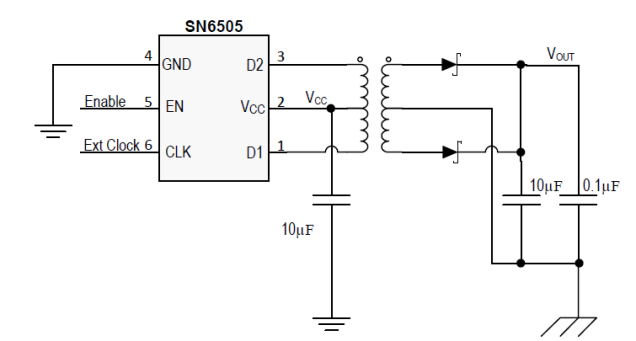
There are several solutions that can be used to create an isolation barrier using a transformer. The push-pull transformer driver in Figure 4-1 operates at a 50% duty cycle, so the transformer coil must be designed accordingly to accommodate a specific input and output voltage. The push-pull circuit also runs open-loop, so there is no feedback mechanism. In some cases, a linear regulator is needed on the secondary side to provide better output voltage regulation. The fly-buck regulator, also known as an asymmetrical half-bridge, is shown in Figure 4-2 has same transfer function as a standard buck regulator, but uses a transformer, similar to the flyback converter. The LC of the buck regulator uses C1 for the output bulk capacitor and the primary side of the isolated transformer, T1. The output voltage is reflected to the secondary side and is derived from the turns-ratio of the transformer. R1 and R2 set the duty cycle of the ½ bridge, which allows more flexibility in choosing an off-the-shelf transformer turns-ratio to accommodate the input and output voltages. Also note that the fly-buck’s frequency can be adjusted with the RT pin and also synchronized to a wide range of switching frequencies. The fly-buck here is limited to about 2 W, because high currents flowing thru the diode on the secondary side can limit regulation due to losses. Opto-couplers are not needed for either topology.
The TPS55010 is an example of a low voltage fly-buck. This device has higher efficiency than the push-pull with lower Rds(on) and also uses primary side feedback to allow flexibility with the magnetics. The frequency can be programmed from 100 kHz to 2MHz and synchronized to an external clock with the clock pin. However, the TPS55010 requires loop compensation, since this is a current mode controlled converter. However, a design calculator on the web that can aid in selecting the compensation components based on the transformer and capacitor selections. For higher efficiency, more output current, and better regulation accuracy, the fly-buck is a better alternative than a push-pull.
The SN6505 is a low noise push-pull driver for designing isolated supplies. It’s an easy-to-use 6 pin device and uses fewer components than a fly-buck. The device is offered with 2 different switching frequencies, 140 kHz and 400 kHz, and can be synchronized to an external clock. It also features a built-in spread spectrum dithering circuit to help with EMI emissions.