SLVAEI9 February 2021 TPS541620 , TPSM5D1806 , TPSM82810 , TPSM82813 , TPSM82816 , TPSM82821 , TPSM82822 , TPSM82823
2 Thermal Performance
Thermal Performance
Power modules typically have the inductor mounted on top of the package. Due to this, in addition to the IC losses, the heat generated from the direct current resistance (DCR) and core losses in the inductor add to the total power dissipated in the package. Under the same operating conditions as a larger discrete solution, in which the IC and the inductor are side by side, the module has the challenge of dissipating more heat through a smaller surface area. This results in a significant temperature increase of the IC within the module, which worsens at high load currents where the amount of power dissipated within the module rises. Since the temperatures of both the inductor and IC have maximum-rated values, there is a limitation on the maximum output current that modules can deliver at higher ambient temperatures.
In order for modules to be competitive with discrete solutions in terms of efficiency and maximum deliverable output currents, it is important that the module solution has a low junction-to-ambient thermal resistance (RƟJA). RƟJA is a measure of how easy it is to move the heat of the module to the ambient environment. RƟJA is a measure of thermal performance.
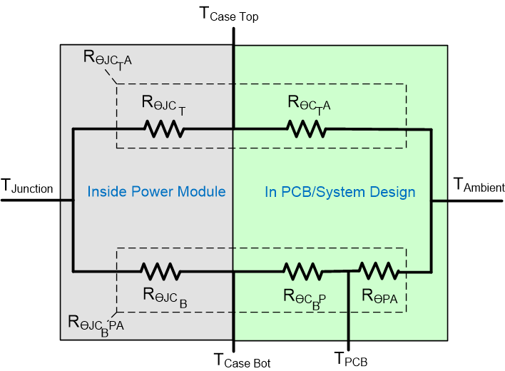
 Figure 2-1 Thermal Resistance from
Junction to Ambient
Since most of the heat of the module is dissipated through RƟJCBPA with little heat being dissipated through the top of the module, RƟJA can be approximated to be equal to RƟJCBPA.

where, RƟJCB is the junction to case metal pad thermal resistance, RƟCBP is the thermal resistance from case metal pad to PCB and RƟPA is the thermal resistance from PCB to ambient.
RƟJCB is minimized during module package development and care should be taken to minimize RƟCBP and RƟPA during PCB design and layout. Adding ground planes, increasing copper layer thickness, and adding vias beneath exposed thermal pads are some of the ways to improve thermal performance through PCB design.
Table 2-1 compares the RƟJA of the module TPSM82822 with the discrete IC of TPS62822. It can be seen that the module has around 20% lower RƟJA compared to the discrete solution on a high-K (JEDEC 51-7) PCB.
| THERMAL PARAMETER | TPS62822 | TPSM82822 |
|---|---|---|
| RƟJA | 114.1 | 92.5 |
Choosing the right inductor also plays an important role in the module performance. The integrated inductor in the TPSM82822 module is chosen based on small size, low DCR, and low core losses.