SLVAF46A May 2021 – January 2023 TPS65988
2 Integrated USB Wall Socket Design
An integrated USB wall socket accommodates USB charging ports on the face plate along with the AC outlet terminals.
 Figure 2-1 Integrated Type-A USB Charging Port
Block Diagram
Figure 2-1 Integrated Type-A USB Charging Port
Block DiagramFigure 2-1 shows different blocks that constitute a conventional USB Type-A charging port on a wall socket. The EMI filter and rectifier block generate high voltage DC from AC mains input. The high frequency isolated fly back controller and synchronous rectifier block provides regulated DC for the charger port. The protection elements are meant for protecting the USB port from faults such as under voltage protection (UVP), over voltage protection (OVP), reverse current protection (RCP) and over current protection (OCP).
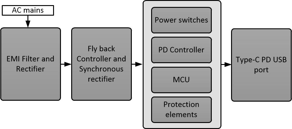
 Figure 2-2 Integrated Type-C PD USB Charging Port
Block Diagram
Figure 2-2 Integrated Type-C PD USB Charging Port
Block DiagramNow, as shown in Figure 2-2 a Type-C PD charging port requires few additional components compared to conventional Type-A port.
- PD controller: To add Type-C PD functionality.
- Power switch: to control the power delivery to the port as per PD specification.
- Protection elements: to protect USB port from faults such as OVP, UVP, OCP, RCP, and so forth.
- MCU: Required in fixed function PD controller to implement customized power policy (if required).
Manufacturers of plugs and sockets have to follow mechanical dimensions defined by the regulatory standards (Eg BS 1363). One electrical gang box is usually of 4”(L)x2.75”(W)x2.5”(D) in size. The actual available area for PCB inside the box will be smaller than this as the gang box behind the front panel has to accommodate thick wires connecting AC terminals on the face plate. Now, with these restrictions, finding additional space for the Type-C PD related components in the wall socket design can be a challenge for system designers.
Today, most of the PD controllers in the market require external power mosfets for controlling power delivery to the Type-C port. System designers using such PD controllers will have to build their own protection circuits around the external power switches with the expense of additional PCB area and BOM. As per Type-C/ PD specification OCP protection is mandatory for Source ports (Type-C PD port that delivers power). TI’s highly integrated dual Port PD controller TPS665988DH comes with integrated power switches and built in protection features, avoiding the need for these additional external components.
USB PD device applications often require customizations in order to achieve desired system behavior. For instance, customization is required in the dual port wall socket design (to be discussed later in this application note) for live power balancing between the ports. Any customization in the core firmware affects reliability, USB PD compliance and also slows down the development cycle. Typically, systems using fixed function PD controllers are required to have an on board microcontroller in this regard, with the TI PD controller being an exception. The GPIO event features of TPS65988DH allow PD system designers to customize the PD controller behavior using GUI software tool without affecting the core PD firmware.