SLVAF46A May 2021 – January 2023 TPS65988
2.5 GUI Configuration
- The first step is to create a new DFP only
(Source only) project by loading the default template
TPS65988DDH_advanced_v6_1_2.tpl.
- Open TPS6598x Configuration Tool and click the Project tab.
- Select TPS65988DDH→Advanced→Downstream Facing Port (DFP) only.
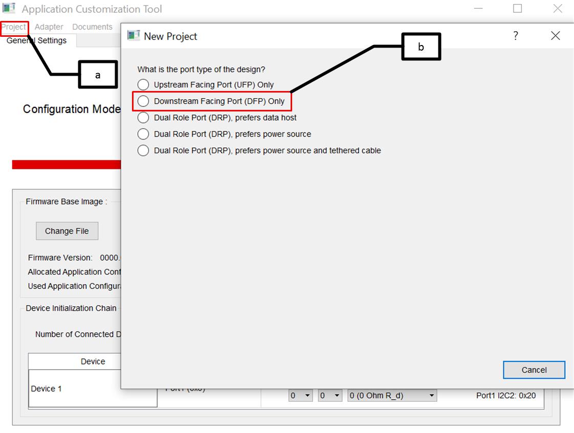 Figure 2-7 Load Template File
 - As shown in Figure 2-6, the application requires two sets of power profiles per port: corresponding 30W
and 60W PDOs. In this step, generate these configurations and map them to virtual
addresses.
- Change Number of Configuration Sets in General Settings to four.
- Rename Configuration Set as
shown below for convenience.
- Virtual Address 1 -> Port-0 30W
- Virtual Address 2 -> Port-0 60W
- Virtual Address 3 -> Port-1 30W
- Virtual Address 4 -> Port-1 60W
- Now, map Configuration sets to Virtual Address as shown in Figure 2-8.
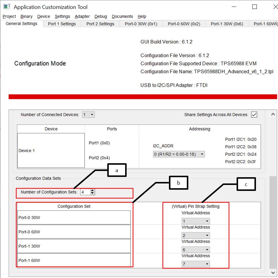 Figure 2-8 Generate Configuration
Sets and Map to Virtual AddressNote: Do not use address 0x00 and 0x04 as they are reserved for port configurations.
 - The App configuration register (0x6C) holds the
index pointing to the application configuration that needs to be loaded when the
GPIO assert/ de-assert and also holds the command channel interface for executing
the PD message task. In this step, modify Port-0 App Configuration Register
to point to the application configuration index Virtual Address 1 on GPIO
high transition (corresponding to application configuration Port-0 30W) and point to
Virtual Address 2 on GPIO high transition (corresponding to application
configuration Port-0 60W) and then execute SSrC task using CMD1 channel.
- Click the Port 1 Settings tab.
- Click the App Configuration Register.
- The index of configurations that need to be loaded on GPIO low/high transition are selected from the drop-down menu below Value tab.
- The default command channel CMD1 (0x08) can be used for executing PD message task.
- Select PD message task SSrC from the drop-down menu to transmit the Source Capability configured in the application configuration space indexed by Virtual Address 1 or Virtual Address 2. Enter !CMD in not Task field to indicate no action.
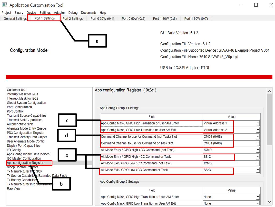 Figure 2-9 App Configuration Register
Entry
 - Similarly, make entry for Port-1 App Configuration Register by referring the pjt file attached.
- Now, configure Transmit Source Capabilities
register (0x32) pointed by Virtual Address indexes. Virtual address 1 is the index
corresponding to 30W PDO.
- Click Port-0 30W (0x1) and then click Adjust Registers.
- From the pop-up box, select Transmit Source Capabilities (0x32) Register.
- Click OK.
- Click Transmit Source Capabilities and make entry for 30W PDO as shown in Figure 2-11.
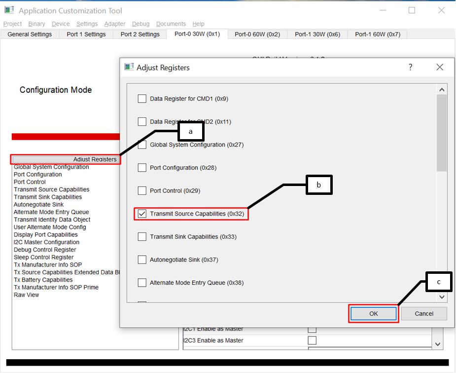 Figure 2-10 Select Transmit Source
Capabilities Register
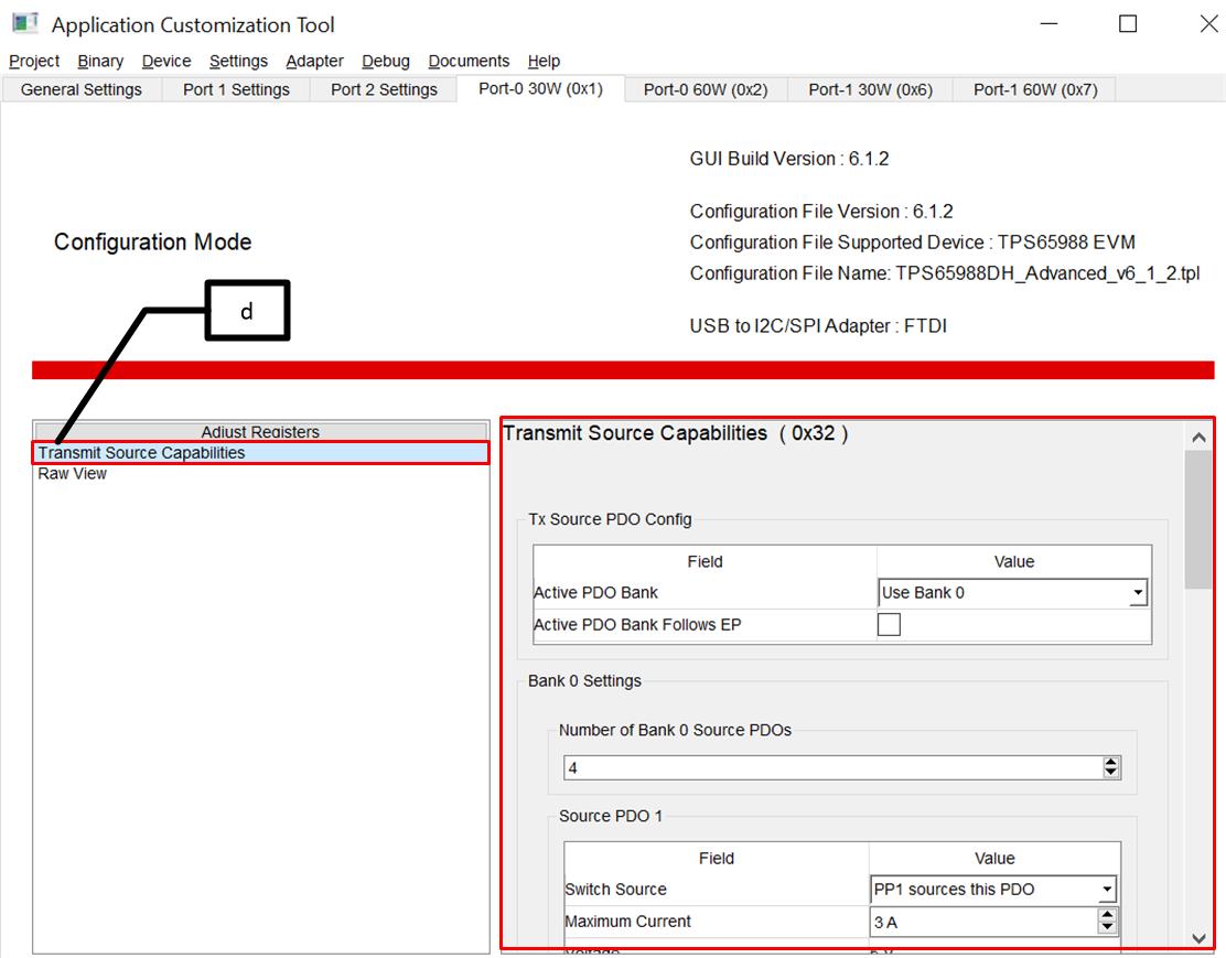 Figure 2-11 Configure Transmit Source
Capabilities
 - Similarly, make entries for remaining Virtual Addresses referring the pjt file attached with this application.
- Map App Config and GPIO events to respective
GPIOs as shown in Figure 2-12.
- Select IO Config Register.
- Map events for each GPIO. Refer to project file for GPIO 2 and 3.
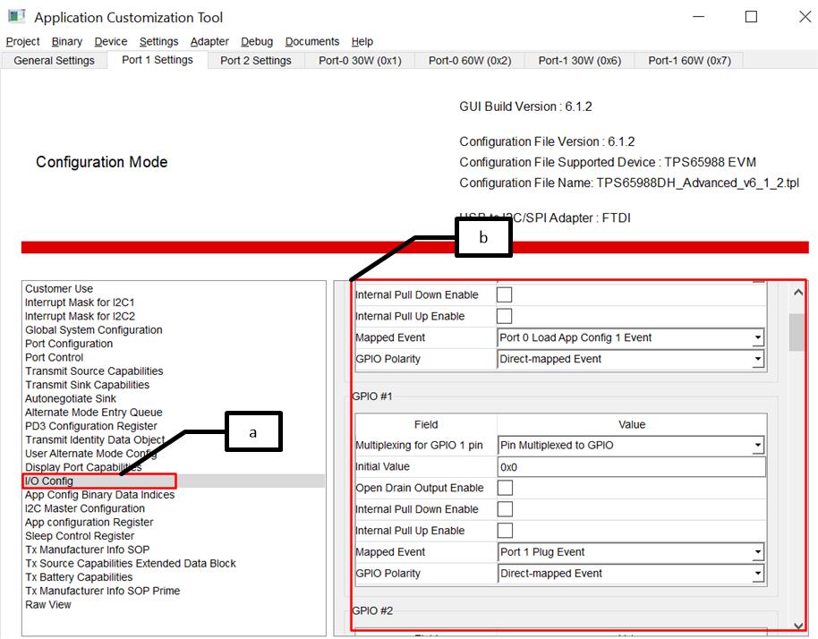 Figure 2-12 GPIO Mapping