SLVUC05A November 2020 – July 2022 TPS25750
- Read This First
- 1Introduction
-
2Unique Address Interface Register Detailed Descriptions
- 2.1 0x03 MODE Register
- 2.2 0x0D DEVICE_CAPABILITIES Register
- 2.3 0x14 - 0x19 INT_EVENT, INT_MASK, INT_CLEAR Registers
- 2.4 0x1A STATUS Register
- 2.5 0x26 POWER_PATH_STATUS Register
- 2.6 0x29 PORT_CONTROL Register
- 2.7 0x2D BOOT_STATUS Register
- 2.8 0x30 RX_SOURCE_CAPS Register
- 2.9 0x31 RX_SINK_CAPS Register
- 2.10 0x32 TX_SOURCE_CAPS Register
- 2.11 0x33 TX_SINK_CAPS Register
- 2.12 0x34 ACTIVE_CONTRACT_PDO Register
- 2.13 0x35 ACTIVE_CONTRACT_RDO Register
- 2.14 0x3F POWER_STATUS Register
- 2.15 0x40 PD_STATUS Register
- 2.16 GPIO Events
- 2.17 0x69 TYPEC_STATE Register
- 2.18 0x70 SLEEP_CONFIG Register
- 2.19 0x72 GPIO_STATUS Register
- 34CC Task Detailed Descriptions
- 4User Reference
- 5Revision History
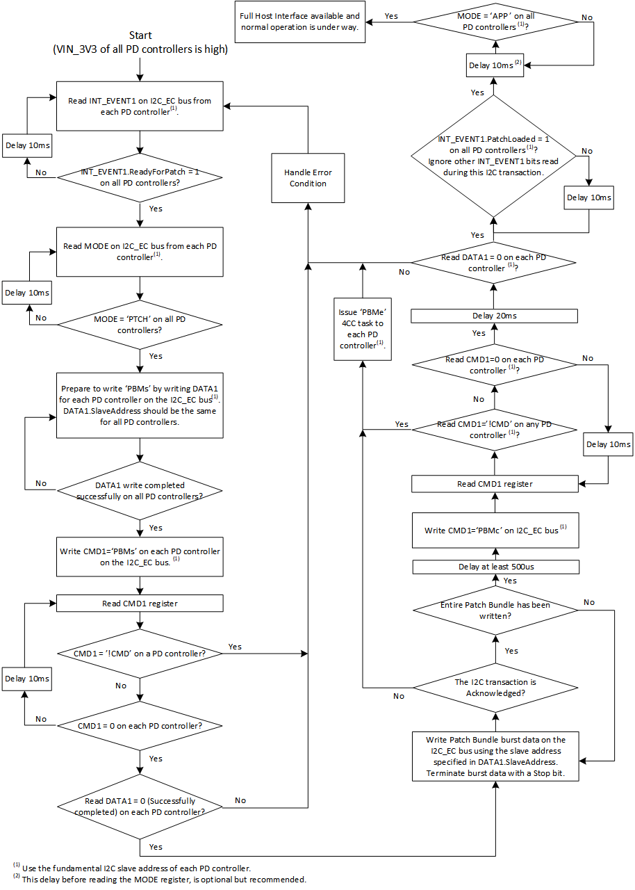
3.3.4 Patch Burst Mode Example
Commands
- PBMs: The 'PBMs' Task starts the patch loading sequence. This task initializes the firmware in preparation for a patch bundle load sequence and indicates what the patch bundle contains.
- PBMc: The 'PBMc' Task ends the patch loading sequence. This command shall be executed after all patch data has been transferred. This task initiates the CRC check on the binary patch data that has been transferred, and if the CRC is successful, the patch_init function contained within the patch is executed. If this Task is sent prior to a 'PBMs' start Task, it indicates to the PD Controller that no patch is available and bypasses the patch process.
- PBMe: The 'PBMe' Task ends the patch loading sequence. This Task instructs the PD controller to complete the patch loading process.
- PTCr: This task resets the patch firmware to the no patch state.
1. The device generates an I2C interrupt, INT_EVENT.ReadyForPatch, indicating that it’s ready for patch. The host shall start the patch download process only after receiving this notification from the device.
2. The host shall start the patch download process by sending a PBMs command to the device.
3. The host shall then transmit the entire patch-bundle data. The host may send the entire Patch Bundle in a single I2C transaction, or it may break it into multiple transactions. The PD controller increments the pointer into its patch memory space with each byte received on the Patch Slave address that was configured as part of the 'PBMs' 4CC Task.
4. The host shall then send the PBMc command to indicate the PD Controller that the patch load sequence is complete. After successful boot sequence, the PD Controller begins application execution.
To execute a 4CC command, the host application shall follow the below sequence:
- If the 4CC command requires an input, the application shall first write the input data into the DataX (0x09 or 0x11) register.
-
The application shall then write the 4CC command characters into the corresponding CmdX (0x08 or 0x10) register.
-
The application can register and waits for CmdXComplete event or repeatedly read the four byte content of CmdX register until it reads
-
0x00' indicating that the command is successfully executed.
-
or, '!CMD' indicating that the command's execution has failed.
-
- If the command is successfully executed, the application shall proceed to read the 'n' byte content of the DataX register which will contain the output.
Execution Flow
Example Code
1.
void AsyncEvtHandlerP11()
{
s_AppContext *const pCtx = &gAppCtx;
I2C_IF_TPS6598xIntDisable(pCtx->i2cPort);
ProcessEvent();
}
static int32_t ProcessEvent()
{
s_AppContext *const pCtx = &gAppCtx;
s_AppData *const pData = &gAppData[pCtx->i2cPort];
uint8_t outdata[MAX_BUF_BSIZE] = {0};
uint8_t indata[MAX_BUF_BSIZE] = {0xFF,0xFF,0xFF,0xFF,0xFF,0xFF,0xFF,0xFF,0xFF,0xFF,0xFF};
s_TPS_IntEvent *pSetEvent = NULL;
s_TPS_IntEvent *pClrEvent = NULL;
int32_t retVal = -1;
#ifdef WORKAROUND_WAIT_AFTER_GAID
if(0 == wait_after_gaid)
{
wait_after_gaid += 1;
/*
* The 100ms delay here is to allow the device to ACK the I2C transactions
* after a cold start
*/
Board_IF_Delay(100000);
}
#endif /* WORKAROUND_WAIT_AFTER_GAID */
retVal = ReadReg(pData->event_reg, REG_LEN_INTEVENT1, &outdata[0]);
RETURN_ON_ERROR(retVal);
/*
* output[0] = Register's size in bytes
* output[1..REG_LEN_INTEVENT1] = Register's content, and hence '&outdata[1]' below.!
*/
pSetEvent = (s_TPS_IntEvent *)&outdata[1];
pClrEvent = (s_TPS_IntEvent *)&indata[0];
if(0 != pSetEvent->cmd1complete)
{
pData->cmdExeInProgress = 0;
pClrEvent->cmd1complete = 1;
}
if(0 != pSetEvent->readyforpatch)
{
pClrEvent->readyforpatch = 1;
SignalEvent(APP_EVENT_READY_FOR_PATCH);
}
if(0 != pSetEvent->patchloaded)
{
pClrEvent->patchloaded = 1;
SignalEvent(APP_EVENT_PATCH_LOADED);
}
/* App events are triggred - The corresponding events of the device can now be cleared */ retVal = WriteReg(pData->clear_reg, REG_LEN_INTCLEAR1, &indata[0]); RETURN_ON_ERROR(retVal);
return 0;
}
2.
static int32_t StartPatchDownloadBurstMode()
{
uint8_t outdata[MAX_BUF_BSIZE] = {0};
s_PBMs_InData pbmsInData = {0};
s_PBMs_OutData *p_pbmsOutData = NULL;
int32_t retVal = -1;
UART_PRINT("Starting Patch Download in Burst Mode\n\r");
retVal = ReadMode();
RETURN_ON_ERROR(retVal);
retVal = ReadVersion(); RETURN_ON_ERROR(retVal); /* If the device is in APP mode, don't allow burst-mode patch download */
if(isDeviceInAppMode())
{
UART_PRINT("Burst mode patching not allowed in APP mode\n\r");
retVal = -1;
goto error;
} /* Wait for CmdComplete event when executing the 4CC commands */
retVal = MaskCmdComplete(1);
RETURN_ON_ERROR(retVal); /* Fill the input, and execute 'PBMs' */
pbmsInData.lrBinSize = gSizeLowregionArray;
pbmsInData.slaveAddress = SLAVE_ADDR_FOR_PATCH_DATA;
pbmsInData.timeout = BURST_MODE_TIMEOUT;
retVal = ExecCmd(PBMs, sizeof(pbmsInData), (uint8_t *)&pbmsInData, \ PBMs_OUTPUT_SIZE, &outdata[0]);
RETURN_ON_ERROR(retVal); /* 'outdata' will contain the command's output after the successful execution of PBMs. */
p_pbmsOutData = (s_PBMs_OutData *)&outdata[1];
if(PBMs_SUCCESS != p_pbmsOutData->patch_start_status)
{
ERR_PRINT(p_pbmsOutData->patch_start_status);
retVal = -1; goto error;
}
error: return retVal;
}
3.
Low region binary 'C' array format can be generated using the Application Customization GUI. tps6598x_lowregion_array and gSizeLowregionArray referenced in the below snippet are taken from this generated file.
static int32_t DownloadDataBurstMode()
{
int32_t retVal = 0;
#ifdef WORKAROUND_IGNORE_CMDxCMPLT_BURST_TX
/*
* Workaround: Device was erroneously sending an unexpected CmdXComplete
* event occationally while in the middle of the patch download process,
* causing the SM to go for a toss.!
*/
MaskCmdComplete(0);
#endif /* WORKAROUND_IGNORE_CMDxCMPLT_BURST_TX */
/*
* tps6598x_lowregion_array and gSizeLowregionArray are defined
* in the 'C' array file that can be created using the
* Application customization GUI
*/
UART_PRINT(".");
SendDataToSlave(SLAVE_ADDR_FOR_PATCH_DATA, gSizeLowregionArray, (uint8_t *)&tps6598x_lowregion_array[0]);
/* Proceed to the next step after the patch is successfully downloaded */
UART_PRINT("\n\r");
SignalEvent(APP_EVENT_PATCH_DOWNLOADED);
return retVal;
}
4.
static int32_t PatchDownloadCompleteBurstMode()
{
s_AppContext *const pCtx = &gAppCtx;
/* PBMc return structure and statuses are exactly same as PTCc */
s_PTCc_OutData *p_pbmcOutData = NULL;
uint8_t outdata[MAX_BUF_BSIZE] = {0};
int32_t retVal = -1;
UART_PRINT("Patch Download Complete\n\r");
#ifdef WORKAROUND_IGNORE_CMDxCMPLT_BURST_TX
MaskCmdComplete(1);
#endif /* WORKAROUND_IGNORE_CMDxCMPLT_BURST_TX */
/* Execute PBMc to indicate to the device that the patch is successfully downloaded */
retVal = ExecCmd(PBMc, 0, NULL, PTCc_OUTPUT_SIZE, &outdata[0]);
RETURN_ON_ERROR(retVal);
/* 'outdata’ will contain the command's output after the successful execution of PBMc. */
p_pbmcOutData = (s_PTCc_OutData *)&outdata[3];
if(p_pbmcOutData->patch_complete_status != PTCc_SUCCESS)
{
ERR_PRINT(p_pbmcOutData->patch_complete_status);
retVal = -1;
goto error;
}
/* Expecting 'PatchLoaded' event */
retVal = I2C_IF_TPS6598xIntEnable(pCtx->i2cPort);
RETURN_ON_ERROR(retVal);
error: return retVal;
}