SLYA073 December 2022 CC1312R , DRV5032 , TMAG5273
2.1 Top-Side Board Overview
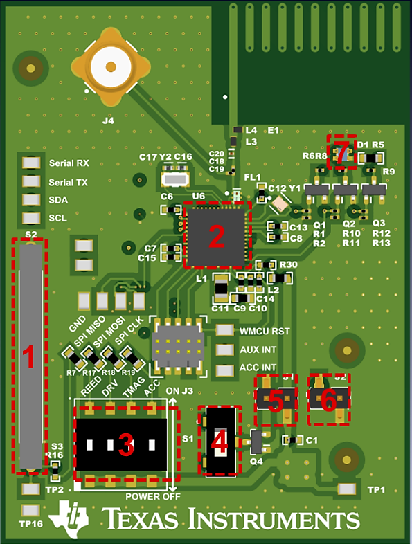
Figure 2-2 shows the top view of the door and window sensor evaluation platform.
 Figure 2-2 Door and Window Sensor
Evaluation Platform Top View
Figure 2-2 Door and Window Sensor
Evaluation Platform Top ViewThe following list describes the labels in Figure 2-2.
- Reed switch – 1-A, single pole single throw (SPST), normally open, axial Reed switch tied to the power source and a GPIO pin of the main MCU.
- CC1312R SimpleLink™ MCU
- Sensor enable dip switches – On and Off slide switches which is used to provide power to each of the sensors onboard when placed in the on position. The off position removes all power for a particular sensor which is helpful in profiling power consumption of only the required sensors.
- Power source selection switch – Selects between coin cell battery power source and the off-board power source.
- Main power current shunt – jumper from power source that can be used to acquire current measurements.
- Off-board power connector – Can be used to provide alternative power to the board in the case where a coin-cell battery is not present. Maximum voltage is 3.3 V from any source.
- RGB LED – used for debug and detection status of the Reed switch and the DRV5032
On the top side of the evaluation platform there are several points of interest for testing. The main MCU is the CC1312R sub-1G wireless MCU. One of the benefits of using a SimpleLink platform aside from the long-range communication is the Sensor Controller Engine (SCE). This allows the main portion of the processor to remain in a low-power sleep mode, only waking up when the processor receives an alert from the SCE indicating activity. This significantly reduces system power consumption and can help increase battery life expectancy.
For the sensors, the Reed switch is placed on top due to the elongated tube that houses the switch itself. All other sensors are placed on the bottom of the board, in proximity to the Reed switch location. One nice feature this board has is the ability to fully remove power from any sensor that does not need to be active, thus removing any quiescent current associated with simply disabling the device and allowing for accurate system-level power consumption data. This is done with the four position slide switches located on the top of the board. A second switch is also located on the top side which allows the user to select the main power source from either the onboard battery or a secondary off-board power source.
Lastly, there is an RGB LED which can be used for debug, but the LED also gives feedback on magnetic field detection with respect to the Reed switch and the DRV5032. The following list summarizes the LED output for different events:
- Color Cycling through RGB: system is setting up communication channels and implementing sensor register setup routine
- Green: No magnetic field detected for either magnetic switch
- Red: Magnetic field detected via Reed switch
- Blue: Magnetic field detected via DRV5032
- Magenta: Magnetic field detected with both Reed switch and DRV5032
This color scheme can be changed within the Sysconfig file for the Code Composer Studio™ (CCS) project, or disabled if an LED is not desired for evaluation (Detection indication is also given via serial console).