SNAU273 December 2022 LMX2820
3.1 Category 1 SYNC Example
The following is a Category 1 SYNC configuration, because:
- M = 1 (Doubler and MULT are not used)
- fOUT is an integer multiple of fOSCIN (6000 / 100 = 60)
- Channel divider is bypassed (output frequency = VCO frequency)
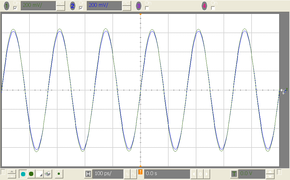
With this configuration, the outputs are in phase after programming the LMX2820 devices. The output phases remain constant if:
- LMX2820 is powered down and powered up again
- VCO is calibrated again
- LMX2820 is reset and re-programmed
 Figure 3-4 Category 1 SYNC Result
Below is another Category 1 SYNC configuration example. This configuration has enabled the Doubler:
- M = 2 (Doubler is enabled)
- Channel divider is bypassed
- fOUT is an integer multiple of M × fOSCIN (6000 / 200 = 30)
- PLL_NUM = 0
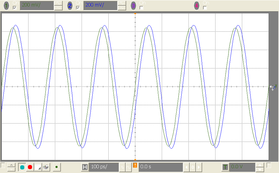
If only one of the LMX2820 devices has the Doubler enabled, although both configurations are Category 1 SYNC, the Doubler introduces addition delay in the input path. This delay is carried forward to the output. As a consequence, the phases of the LMX2820 outputs are not exactly in phase. To get exact phase match between multiple LMX2820 devices, the configurations should be identical.
 Figure 3-6 Phase Offset Due to Unsymmetrical Configuration