SNOU177 December 2020 LM74700-Q1
2.3 Schematic
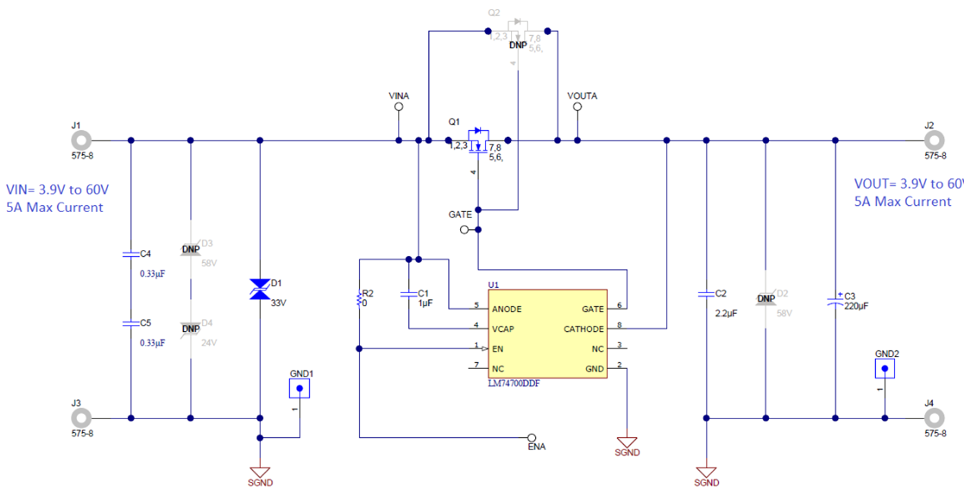
Figure 2-3 illustrates the EVM schematic.
 Figure 2-3 LM74700DDFEVM Schematic
SNOU177 December 2020 LM74700-Q1
Figure 2-3 illustrates the EVM schematic.
 Figure 2-3 LM74700DDFEVM Schematic