SNVU695A June 2020 – January 2022 LP87702-Q1
4 Measurements
Test data can be found in the Application Curves section 8.2.4 of the LP87702-Q1 Dual Buck Converter and 5-V Boost With Diagnostic Functions datasheet for the LP87702K-Q1. Similar data for the preregulator can be found in the section 9.2.3 Application Curves of LM61460-Q1 Automotive 3-V to 36-V, 6-A, Low EMI Synchronous Step-Down Converter datasheet.
Additional bench test data for LP87702K-Q1 efficiency in specific conditions for this power tree can be seen in this section. Figure 4-1, Figure 4-2, and Figure 4-3 show the efficiency measurement results for the LP87702K-Q1.
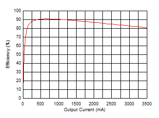 Figure 4-1 LP87702K-Q1 Buck Efficiency with VOUT = 1.8 V, VIN = 3.3 V, 25°C
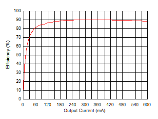 Figure 4-3 LP87702K-Q1 Boost Efficiency with VOUT = 5.0 V, VIN = 3.3 V, 25°C
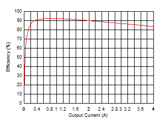 Figure 4-5 TPS62811-Q1 Efficiency with VOUT = 1.2 V, VIN = 3.3 V, fsw = 2.25 MHz, 25°C
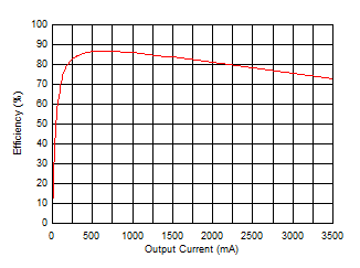 Figure 4-2 LP87702K-Q1 Buck Efficiency with VOUT = 1.0 V, VIN = 3.3 V, 25°C
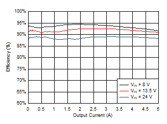 Figure 4-4 LM61460-Q1 Efficiency with VOUT = 3.3 V, fsw = 2.1 MHz, 25°C
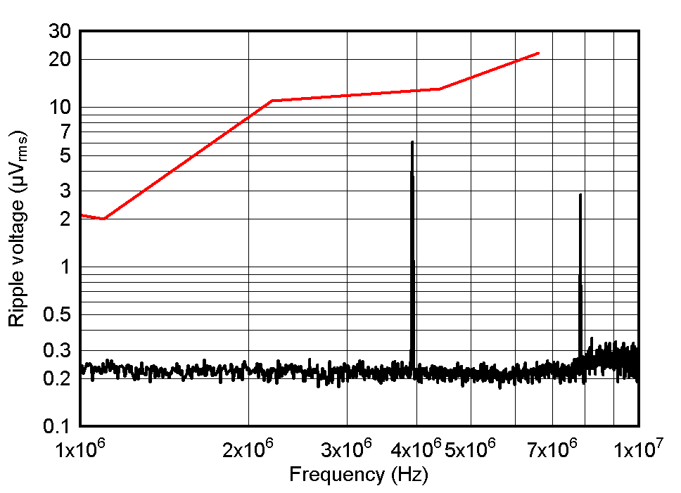 Figure 4-6 LP87702K-Q1 1-V Ripple Performance Against AWR Ripple Specification with MPZ2012S101A Ferrite