SPRAD55 March 2023 TMS320F2800132 , TMS320F2800133 , TMS320F2800135 , TMS320F2800137 , TMS320F2800152-Q1 , TMS320F2800153-Q1 , TMS320F2800154-Q1 , TMS320F2800155 , TMS320F2800155-Q1 , TMS320F2800156-Q1 , TMS320F2800157 , TMS320F2800157-Q1 , TMS320F280021 , TMS320F280021-Q1 , TMS320F280023 , TMS320F280023-Q1 , TMS320F280023C , TMS320F280025 , TMS320F280025-Q1 , TMS320F280025C , TMS320F280025C-Q1 , TMS320F280033 , TMS320F280034 , TMS320F280034-Q1 , TMS320F280036-Q1 , TMS320F280036C-Q1 , TMS320F280037 , TMS320F280037-Q1 , TMS320F280037C , TMS320F280037C-Q1 , TMS320F280038-Q1 , TMS320F280038C-Q1 , TMS320F280039 , TMS320F280039-Q1 , TMS320F280039C , TMS320F280039C-Q1
3 Hardware
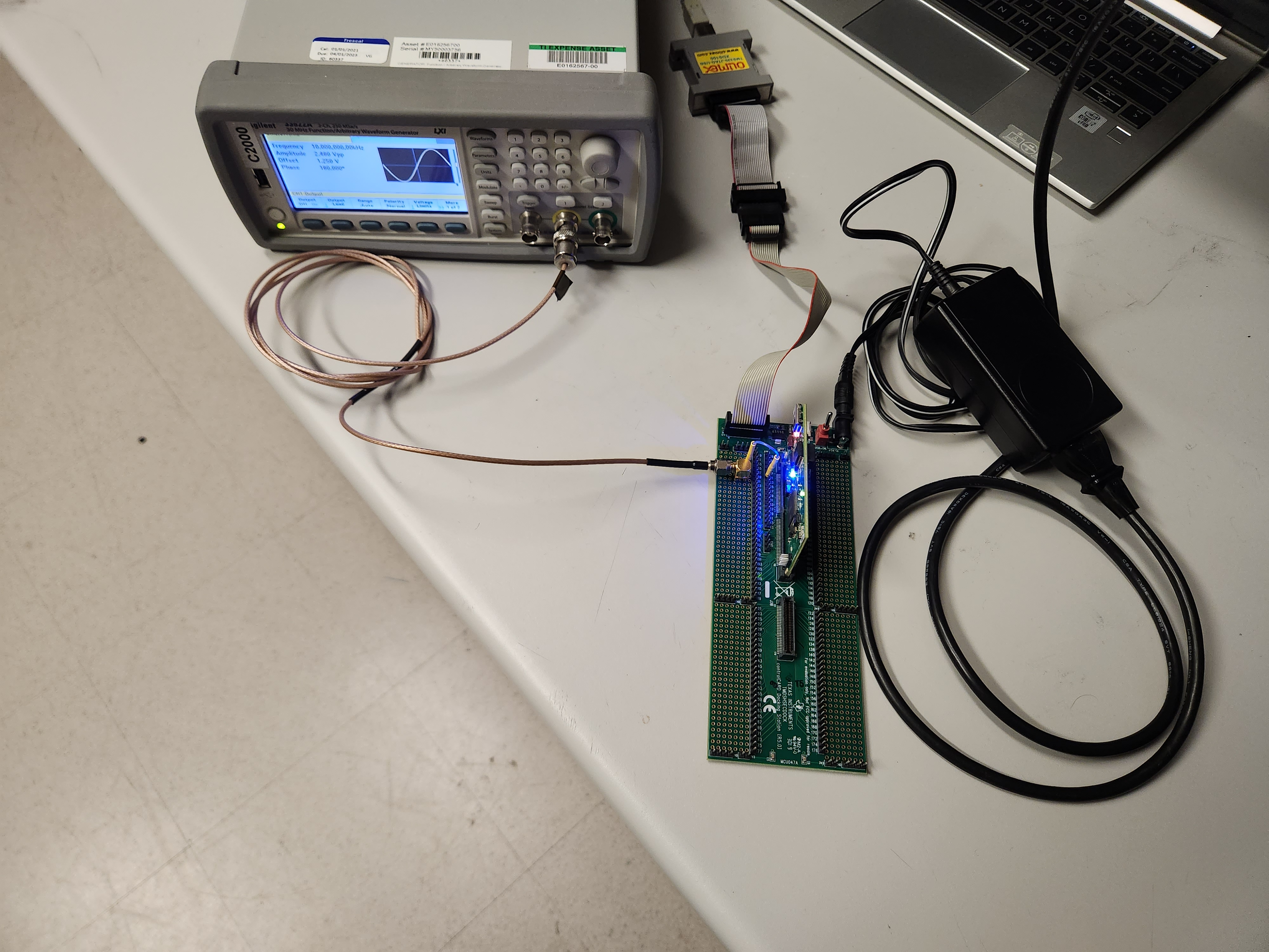
For the purpose of testing ADC oversampling, a TMDSCNCD280039C controlCARD was used to convert the input sine wave into digital values. To configure the reference voltage VREF and JTAG for the controlCARD, see the TMS320F280039C controlCARD Information Guide. To keep the setup simple while reducing possible sources of error, the internal 2.5 V reference was used. If the external VREF is used, extra steps must be taken. For more information regarding VREF, see the Voltage Reference chapter in the ADC chapter of the TMS320F28003x Real-Time Microcontrollers Technical Reference Manual.
The hardware for ADC sampling can reduce environmental and signal noise when configured properly. In the context of evaluating oversampling performance, equipment can be a source of noise. Use signal sources with a high resolution and follow practices for reducing noise in the system for a validation setup. For this application note, the Agilent AG33522A Arbitrary Waveform Generator (AWG) was used as the signal source. In general, a signal source with a higher resolution than the ADC produces the best results. To reduce possible deviations in obtained ENOB values, follow the best layout practices for analog circuits. ADC input conditioning also plays a role in improving the accuracy of ADC itself. For details on input conditioning, see ADC Input Evaluation for C2000™ MCUs. For PCB layout design recommendations, see Hardware Design Guide for F2800x C2000™ Real-Time MCU Series.
 Figure 3-1 Overall Hardware Setup
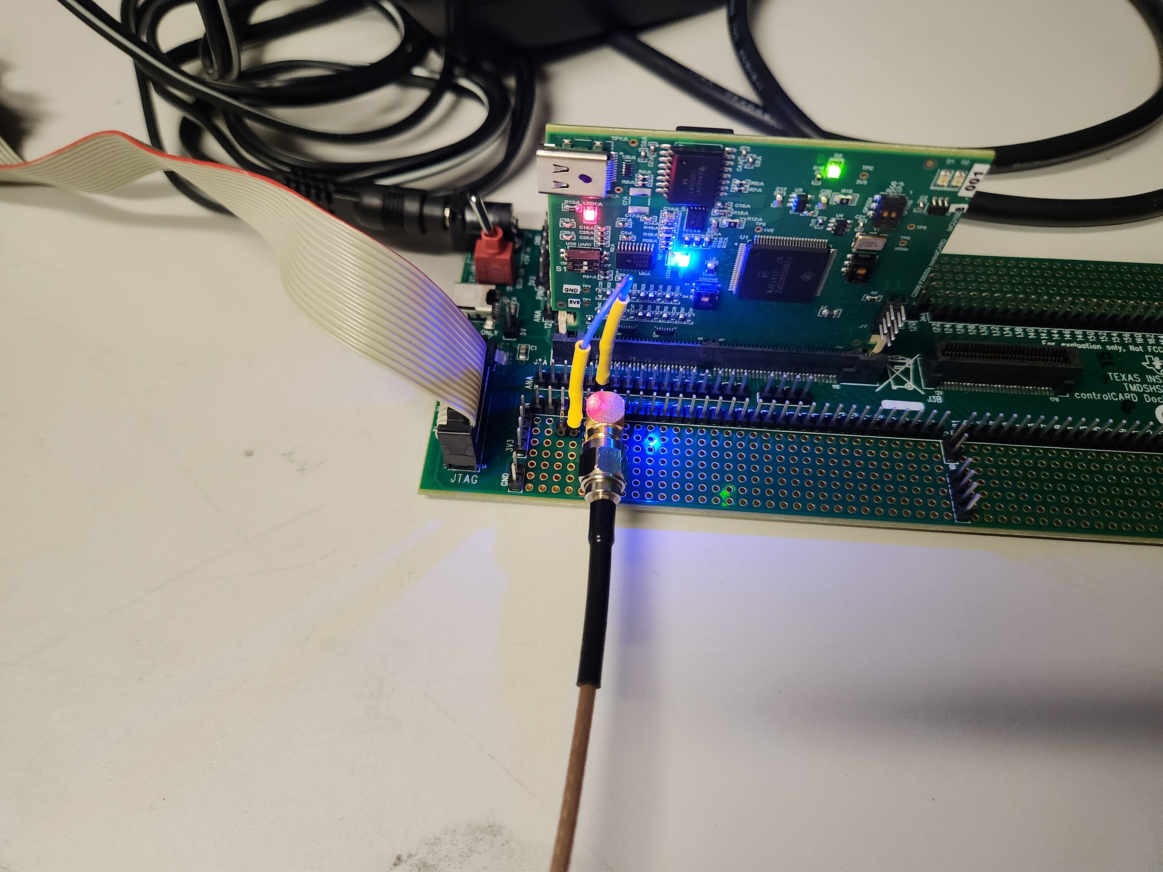
 Figure 3-2 Wiring Setup