SPRUIK4A September 2018 – June 2019 TMS320F280021 , TMS320F280021-Q1 , TMS320F280023 , TMS320F280023-Q1 , TMS320F280023C , TMS320F280025 , TMS320F280025-Q1 , TMS320F280025C , TMS320F280025C-Q1 , TMS320F280040-Q1 , TMS320F280040C-Q1 , TMS320F280041 , TMS320F280041-Q1 , TMS320F280041C , TMS320F280041C-Q1 , TMS320F280045 , TMS320F280048-Q1 , TMS320F280048C-Q1 , TMS320F280049 , TMS320F280049-Q1 , TMS320F280049C , TMS320F280049C-Q1 , TMS320F28075 , TMS320F28075-Q1 , TMS320F28076 , TMS320F28374D , TMS320F28374S , TMS320F28375D , TMS320F28375S , TMS320F28375S-Q1 , TMS320F28376D , TMS320F28376S , TMS320F28377D , TMS320F28377D-Q1 , TMS320F28377S , TMS320F28377S-Q1 , TMS320F28378D , TMS320F28378S , TMS320F28379D , TMS320F28379D-Q1 , TMS320F28379S
-
C2000 Software Frequency Response Analyzer (SFRA) Library and Compensation Designer in SDK Framework
- Trademarks
- 1 Introduction
- 2 Installing the SFRA Library
- 3 Module Summary
- 4 Compensation Designer
- 5 Case Study
- 6 Running Software Test Bench Example for SFRA
- 7 Using SFRA Without SFRA GUI Integration
- 8 FAQ
- Revision History
3.6 SFRA GUI Options and How to Run
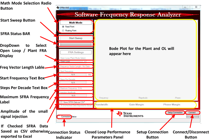
The SFRA GUI can be used to start the frequency sweep and display the measured frequency response. Figure 6 illustrates the different options that are presented.
- MATH Mode Selection Radio Button: This box must be selected appropriately according to the version of SFRA library being used on the MCU. For F28377 and F28004x as they are floating point devices, floating point check box must be checked.
- Setup Connection Button: This button is used to select the COM port and set the baud rate. Click on this button and a pop up window requests a Baud Rate selection, which is typically set to 57600. If the device is connected, click “Refresh Comports” and select the serial comport that the target is using.
- If the comport that the target is connected to is known, please select it.
- If not, and to find a valid comport, go to:
- Control Panel → System → Device Manager → Ports (COM and LPT)
- If using a serial port directly connected to a PC, look for a comport that shows up as “Communications Port” and select this it in the Setup Connection window. If using a USB to Serial adapter, look for the comport that shows “USB Serial Port”, then select this it in the Setup Connection window.
Uncheck “Boot on Connect” to use the GUI in conjunction with a project running from RAM in Code Composer Studio or when using a target that has been flashed with a working SFRA project.
- Connect and Disconnect Button: Once the Math mode is selected appropriately and COM port for the communication is selected, click this button to Connect to the MCU. This is the same button that is used for disconnection from the MCU.
- Connection Status Indicator: This indicates whether the connection was successfully established or if there were any problems.
- Frequentcy Vector Length Label: Once connected, this label shows the length of the FRA array that is programmed on the MCU.
- Start Frequency Text Box: This box shows the start frequency of the SFRA sweep. This can be changed by the user by entering a value in the text box and clicking enter. (Note the value on the controller side is only updated once the user starts a SFRA sweep).
- Steps Per Decade Text Box: Specifies the number of frequency points that FRA is performed per decade.
- Maximum SFRA Frequency Label: This is the maximum frequency until the SFRA will be performed. This is a function of the start frequency, the steps per decade and the frequency length.
- Start Sweep Button: Click this button to begin a frequency sweep on the controller.
- SFRA Status Bar: Indicates the progress of SFRA sweep.
- Drop Down Menu to Select Open Loop or Plant Frequency: Response to be displayed on the panel to the right.
- Closed Loop Performance Parameters Panel: If SFRA is performed on the closed loop, this panel displays the bandwidth, gain margin and the phase margin of the closed loop system.
 Figure 6. SFRA GUI Options