SWRA578B October 2017 – April 2020 CC1312PSIP , CC1312R , CC1314R10 , CC1352P , CC1352P7 , CC1352R , CC2620 , CC2630 , CC2640 , CC2640R2F-Q1 , CC2642R , CC2642R-Q1 , CC2650MODA , CC2652P , CC2652R , CC2652R7 , CC2652RB , CC2652RSIP
2 Measurement Conditions
The measurements were done on projects generated from Sensor Controller Studio without any modifications. The devices were measured without any external disturbance, which is no flow for the flow meter or no movement on the accelerometer, unless specified. Current measurements were done on an Agilent N6705B DC Power Analyzer. The measurements were done in a room temperature environment, with a supply voltage of 3.3 V.
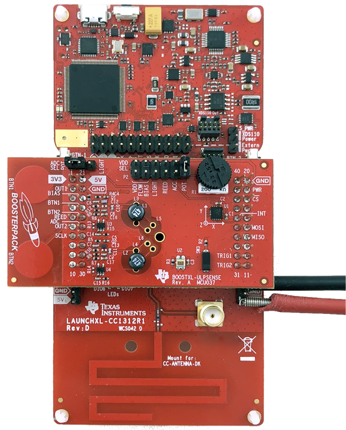
 Figure 2. Measuring on a LAUNCHXL-CC1312R1 with a BOOSTXL-UPLSENSE
 For the current measurement on the LAUNCHXL-CC1312R1 and BOOSTXL-ULPSENSE, all jumpers on the Launchpad are removed, and only the jumpers needed for the test is kept on the BOOSTXL-ULPSENSE. For example for the Potmeter measurement, only the jumper powering the potmeter and the ADC Sel jumper is kept on. The leads of the Agilent N6705B is connected to the 3V3 and GND pins, as shown in the picture above.
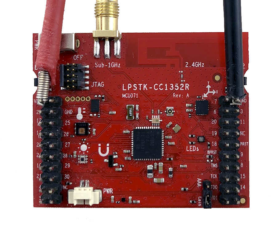
On the LPSTK-CC1352R, the battery is disconnected and JTAG ribbon cable removed. The Agilent N6705B is connected to the VDD and GND pin, as shown in the picture below. The current averages were measured using the Keysight 14585A Control and Analysis Software.
You can read more about power measurements in Measuring CC13xx and CC26xx Current Consumption.
For the measurements on the LAUNCHXL-CC1312R1, each reported current value is the average of 10 measurements on four boards, for a total of 40 measurements. On the LPSTK-CC1352R, each reported current value is the average of 10 measurements on two boards, for a total of 20 measurements.
 Figure 3. Measuring on a LPSTK-CC1352R
 The application report uses the following software and hardware to find the current consumption of the Sensor Controller.