TIDT249 September 2021
3.5 Thermal Data
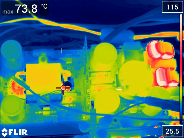
The following image is taken under full load operation. All of the significant heat generation components are connected to the cold plate on the bottom side of the board. The hottest components visible in this image come from the common-mode inductors in the EMI filter. These parts have no access to the cold plate and receive all their cooling via the ambient air.
 Figure 3-7 Top Side Thermal Image
GaN FET temperatures are provide by means of the onboard temperature sensors inside the LMG3522 devices. Under full load conditions, all FET temperatures are less than 75°C.
Table 3-1 lists the GaN FET temperature measurements under the following conditions:
- VIN,AC: 240 V
- VDC,LINK: 400 V
- Coolant temperature: 33°C
| GaN FET | Temperature (°C) |
|---|---|
| PFC | 66.8 |
| CLLLC Primary (350 V/19 A) | 58.1 |
| CLLLC Secondary (350 V/19 A | 59.5 |
| CLLLC Primary (300 V/19 A) | 61.0 |
| CLLLC Secondary (300 V/19 A) | 74.0 |
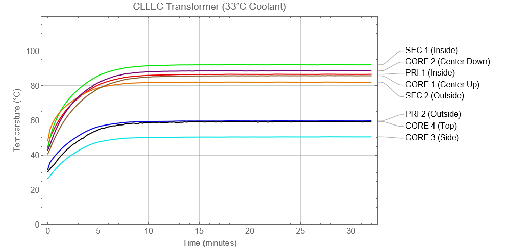
Figure 3-8 shows the critical transformer temperatures under the following conditions:
- Coolant Temperature: 33°C
- Transformer temperature measurement locations
- PRI 1 - Measured on the inside surface of the primary winding
- PRI 2 - Measured on the outside surface of the primary winding
- SEC 1 - Measured on the inside surface of the secondary winding
- SEC 2 - Measured on the outside surface of the secondary winding
- CORE 1 - Measured on the top of the core center leg
- CORE 2 - Measured on the bottom of the core center leg
- CORE 3 - Measured on the side of the core
- CORE 4 - Measured on the top of the core
 Figure 3-8 CLLLC Transformer Temperatures