TIDUAY6E November 2015 – March 2020
4.1.2.3.4.4 Running the Code
- Run the project by clicking on
 .
. - Clear the inverter trip by setting the clearInvTrip variable to 1.
- Set rlyConnect to 1 to connect the relay.
- Set a small current command of 0.02 for invVoRef.
- Slowly raise the DC bus.
- Observe that the invVoRef will appear square in shape to begin with, and as the DC bus is raised, it will take a clean AC waveform shape. Raise the DC bus slowly up to 50 V.
- If the clean AC waveform shape does not appear, revisit the compensation design for the voltage loop.
- Once the closed loop operation is verified, raise the DC bus to the operating voltage to approximately 380 V.
- Increase the invVoRef to 0.25 gradually in steps of 0.05.
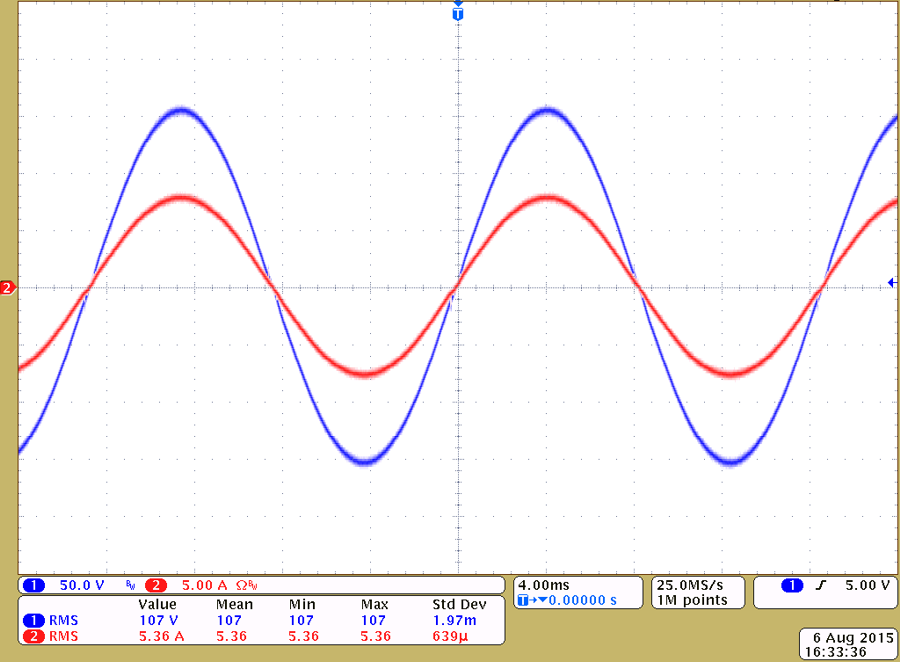
- Observe a regulated voltage at the output, which will be similar to as shown in Figure 34.
- The voltage compensator design is verified.
- Set the invVoRef to zero.
- Reduce the DC bus to zero.
- Set rylConnect to zero to disconnect the relay.
- Fully halting the MCU when in real-time mode is a two-step process.
- Halt the processor and clicking the halt button
 on the toolbar, or by using Target → Halt.
 - Take the MCU out of real-time mode by clicking the clock button
 .
. - Reset the MCU by clicking
 .
. - Close the CCS debug session by clicking Terminate Debug Session
 , or by using Target → Terminate all.
 - The steps above may be repeated by connecting a non-linear load to the output of the inverter.
A quick verification of the closed loop operation can be done by increasing the DC Bus further, but the output voltage AC will regulate at a fixed voltage set at 0.02 by invVoRef. Because this is an AC Build, the expressions window values will constantly change and hence cannot be used to infer on a closed loop operation.
Note in Figure 34 the output is being regulated at full power for this design, and this is not be the exact power level one will reach following the previous steps. Figure 34 is shown as an illustration of full power operation which is at maximum power level.
VAC = 110 VRMS, POUT = 589 W, THD = 0.36%, and efficiency = 96.9% (blue is voltage, red is current).
 Figure 34. Output Voltage Regulated With Linear Load in Build 3