TIDUC26A April 2022 – April 2024
2.2.4 Magnetic Dial Implementation
The TMAG5273 is a 3D Hall-effect sensor used to implement the dial in this design. Being a 3D device allows the device to detect the angle and magnitude of the magnet which enables the push-button functionality on the dial. The integrated CORDIC engine of this device makes angular position sensing easy to implement in this application. The angle of magnet is reported through the device register so no calculations are needed from the MCU. Two similar alternatives that can be used in this application are the TMAG5170-Q1 and TMAG5173-Q1. Both devices offer similar functionality while also providing an automotive-qualified option. All these devices have the built-in CORDIC engine and reports the magnet angle and magnitude through the registers. The three parts are slightly different in that the TMAG5170-Q1 and TMAG5173-Q1 are high precision devices that use SPI and I2C respectively for communication while the TMAG5273 is a general purpose low power device that communicates over I2C. This reference design does not need high resolution to display the angle and has I2C as the main communication protocol so the TMAG5273 was chosen. If automotive qualification is needed, the TMAG5170-Q1 or TMAG5173-Q1 can be used instead.
The magnet used in this device is an N42 diametric cylinder measuring 1/4th in diameter by 1/8th inch thick. This magnet was chosen because the magnet provides an input that uses a significant portion of the full-scale output range. This provides a better SNR performance for the device when used at a desirable distance for the design while still being small and it is easy to obtain.
 Figure 2-5 Magnetic Field Strength Over
Distance
Figure 2-5 Magnetic Field Strength Over
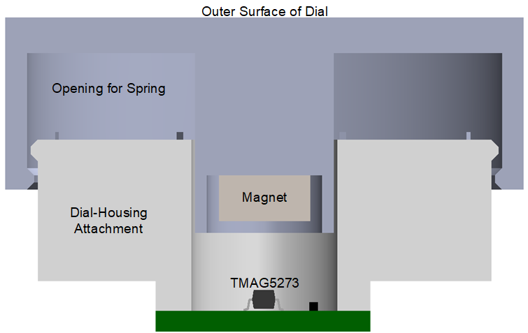
DistanceThe push functionality of the dial is achieved by adding a spring to the design. Most springs are ferromagnetic and interact with the magnetic field but the magnet chosen for this design has a field strong enough that the spring can still be implemented without needing to find a specific non-ferromagnetic version. However, the decrease in field strength also reduces the SNR for this design. This is combated by implementing averaging in the magnetic measurement. The TMAG5273 has a register setting that can be used to change the averaging of the sensor data. Since high speed measurements are not needed in this application, the maximum averaging is chosen for consistent results. Alternatively, the averaging can be turned down to the necessary value and the sleep timer in the device can be used to put the device in low-power mode between samples for lower power applications.
 Figure 2-6 Magnetic Dial Push Button
Stackup
Figure 2-6 Magnetic Dial Push Button
StackupKnowing the distance between the magnet and the sensor as well as the magnet properties, the angle error can be estimated using the Angle Error Calculation Tool. However, since this application does not require a fast sampling rate, the CORDIC algorithm with a high sample averaging applied gives accurate enough information about the position of the dial.