TIDUD31B May 2017 – September 2019
4.4.1.1 Angle Estimation with TDM-MIMO and Velocity Ambiguity
For 2 Tx antenna TDM-MIMO, phase compensation needs to be done for the antenna samples received from the 2nd Tx antenna,
∆
φ
=
2
π
l
2
N
, where
l
=
[
-
N
2
,
.
.
.
,
N
2
-
1
]
is the Doppler index for the detected object, and N is the length of Doppler FFT.
In the case of velocity ambiguity, let v be the radial velocity of the detected object with Doppler index l from CFAR module. l’=l+i*N will represent radial velocity of v’=v+i*Vr,max, where i is an integer number, and l’ will be physically the same as l caused by velocity ambiguity. In turn, the phase compensation for 2nd for v’ will be
∆
φ
'
=
2
π
l
'
2
N
=
∆
φ
+
i
*
+
π
If we examine the formula above carefully, there are only 2 possible values of Doppler compensation for antenna samples from 2nd Tx antenna: H1=exp(-j*(Δφ+(2*k* π)) = exp(-j*Δφ), or H2=exp(-j*(Δφ+((2*k+1)* π)) = -exp(-j*Δφ).
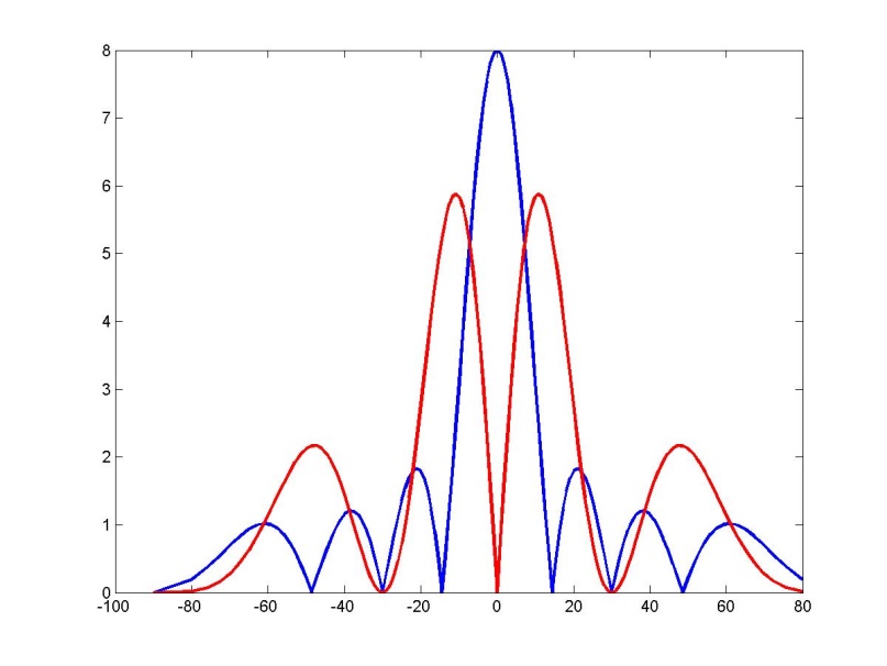
In angular spectrum domain, as shown in Figure 16, when we apply Doppler compensation that correctly reflects the phase rotation from the true Doppler, we will see a spectrum shape in the blue curve, while the red curve represents the angular spectrum from compensation with a wrong hypothesis.
In the low level processing chain, we used a simple technique of just applying these two hypotheses of compensation factor to the antennas samples from 2nd Tx antenna, performing 2 angle estimations on 2 sets of data, and choosing the angle estimate corresponding to the larger peak from the angular spectrum. We call this angle correction for Vmax extension.
 Figure 16. Angular spectrum comparison for antenna samples compensated with 2 hypotheses