TIDUD31B May 2017 – September 2019
6.1 Test Setup
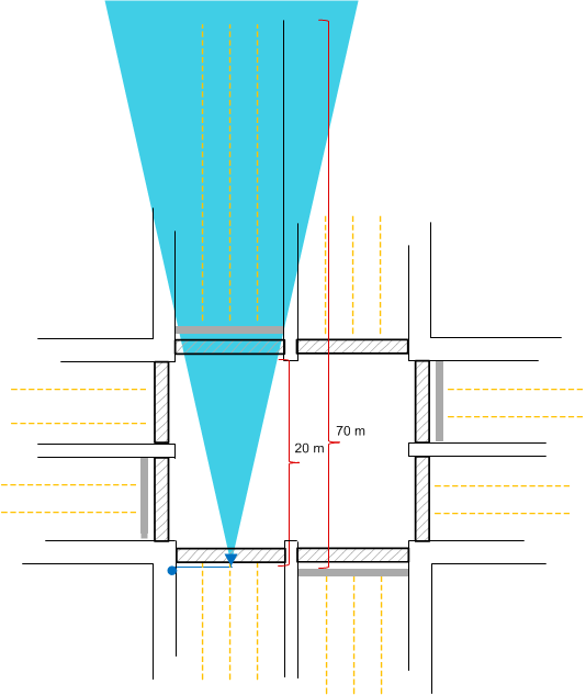
In order to test traffic monitoring system, a test environment was constructed to approximate the scenes calculated from the geometry analysis. Figure 22 shows this test environment, which consists of a mark off for a four or five lane roadway with approximately 70 m of roadway length.
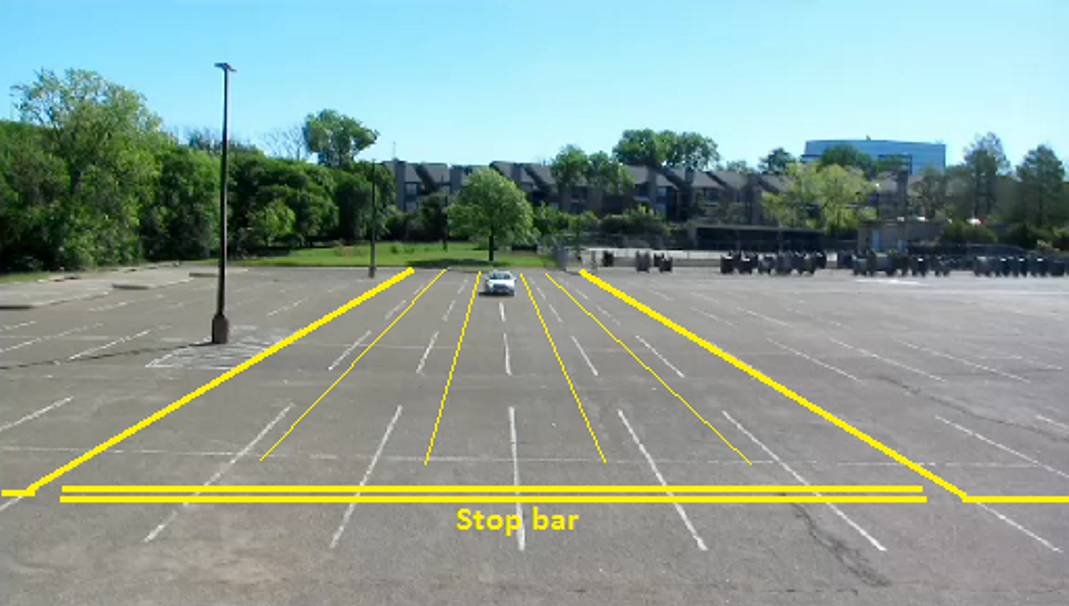
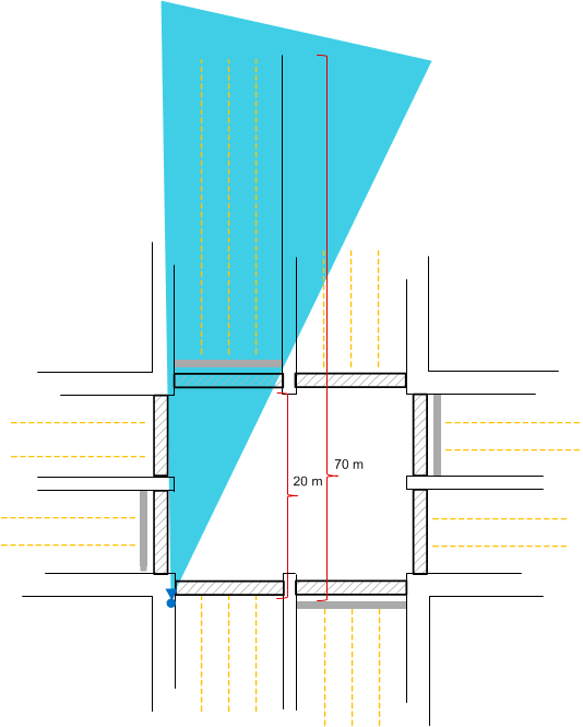
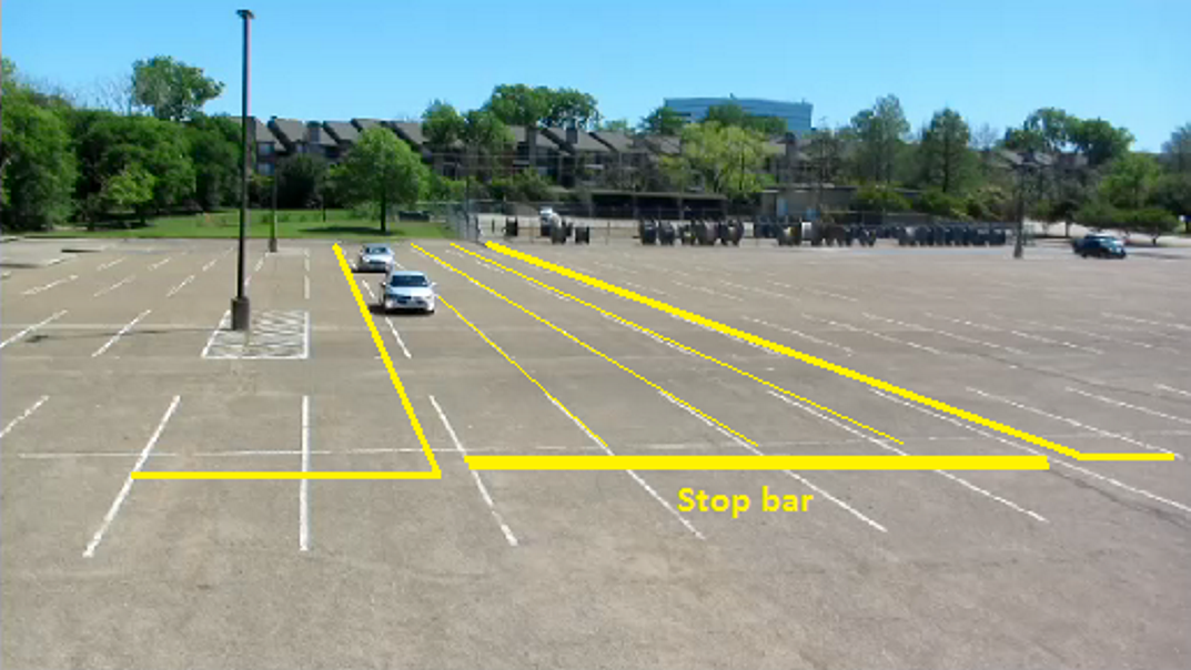
A stop bar was assumed to exist 20 m along the roadway as shown in Figure 23. Two sensor mounting positions were then defined based on the elevation and azimuth field of view of the IWR1642 EVM. One sensor mounting position was situated at 4.9 m above the ground over the center of the five lane roadway. The second sensor mounting position was situated at 4.9 m above the ground but placed off to the side of the four lane road as shown in Figure 24. Simulating a pole mount on the side of the road, the sensor was placed at a 20-m longitudinal distance from the stop bar and 2 m off to the side of the road with an approximately 10° azimuth angle towards the road as shown in Figure 25. In both cases the downtilt angle of the sensor was adjusted so that the field of view included about 5 meters in front of the stop bar at the near end of the road, as well as the far end of the road section which was approximately 70 meters away. This essentially simulated 50 meters of approach beyond the stop bar.
 Figure 22. Test Setup Schematic Layout: First Sensor Mount
  Figure 23. Test Setup Ground Truth First Sensor Mount
  Figure 24. Test Setup Schematic Layout: Second Sensor Mount
  Figure 25. Test Setup Ground Truth Second Sensor Mount