TIDUEG2C March 2019 – March 2020
3.2.2.2.7 Measure SFRA Plant for Current Loop
- Now, return to the SYSCFG page, and select current in the SFRA options to measure the current loop plant.
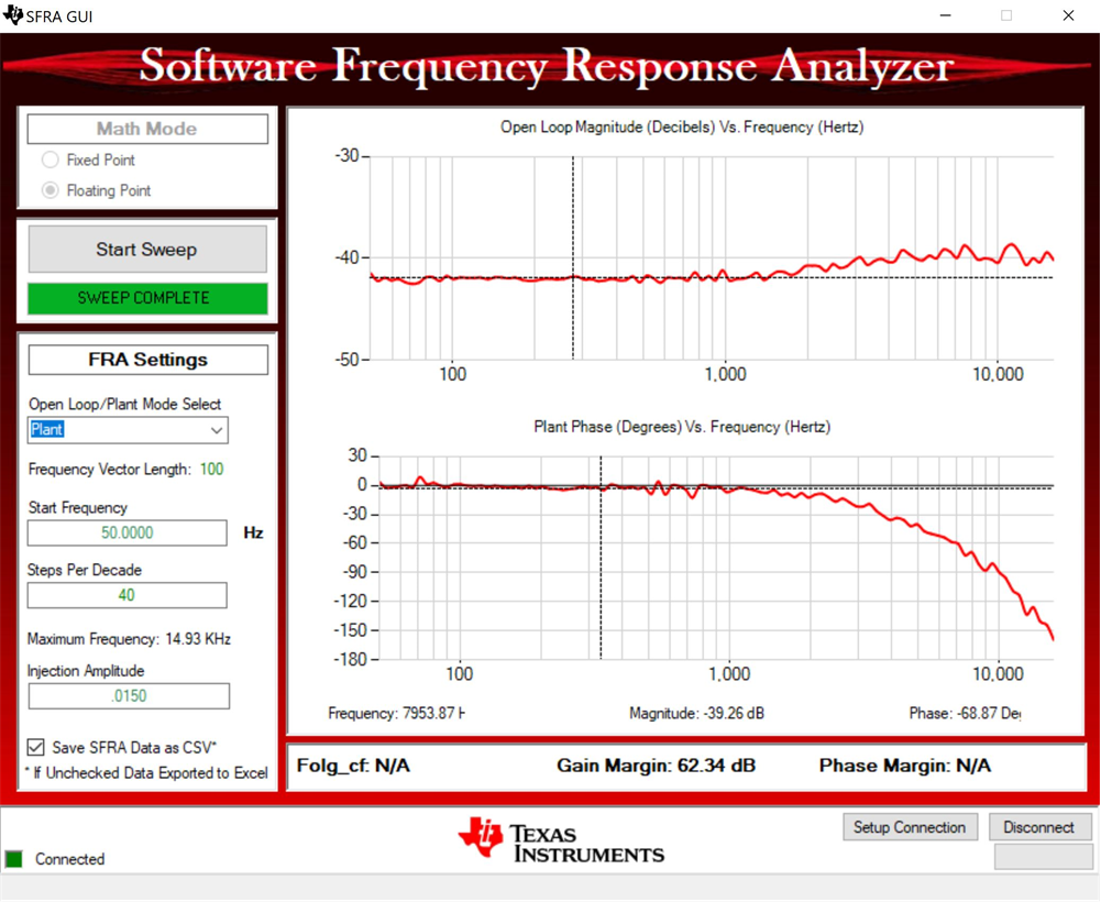
- Rebuild the project, and reload the project. Repeat step 3 (in Section 3.2.2.2.1) to step 2 (in Section 3.2.2.2.5). This time, the SFRA sweep will measure the plant for the current loop. Save this CSV file for use later in the Lab 3. The user can measure this at multiple points to ensure all operating conditions are covered, Figure 44shows the measurement of the current loop plant at 500kHz.
- This completes the check for this build, the following items are verified on successful completion of this build:
- Sensing of voltages and currents and scaling to be correct
- Interrupt generation and execution of the build 1 code in ISR1, ISR2, and ISR3
- PWM driver and switching
- Plant measurement for current and voltage loop
- The controller can now be halted and the debug connection terminated.
- Fully halting the MCU when in real-time mode is a two-step process. First, halt the processor by using the Halt button on the toolbar
 , or by using Target → Halt. Then, take the MCU out of real-time mode by clicking on
  . Finally, reset the MCU
  .
. - Close the CCS debug session by clicking on Terminate Debug Session
 (Target → Terminate all).
Figure 44. SFRA Plant Measurement for the Current Loop at Vprim 400V, Vsec 295V, Switching Frequency at 500kHz and 1887W 
