TIDUEG2C March 2019 – March 2020
3.2.2.4.1 Setting Software Options for Lab 4
- If using the powerSUITE page, go to step 2; otherwise, jump to step 8.
- powerSUITE Settings: On the powerSUITE page,
- Select under the “Project Options” section “Lab 3 : Closed Loop: Current” for the Lab.
- Under “Tuning”, select SFRA to run on the current loop using the drop-down box. Save the page.
- Under Control Loop Design, options for the current loop tuning will automatically be selected,
Tuning → Comp Number 2 → DF22. - Save the page by “Ctrl-S” and click on the Compensation Designer button
 .
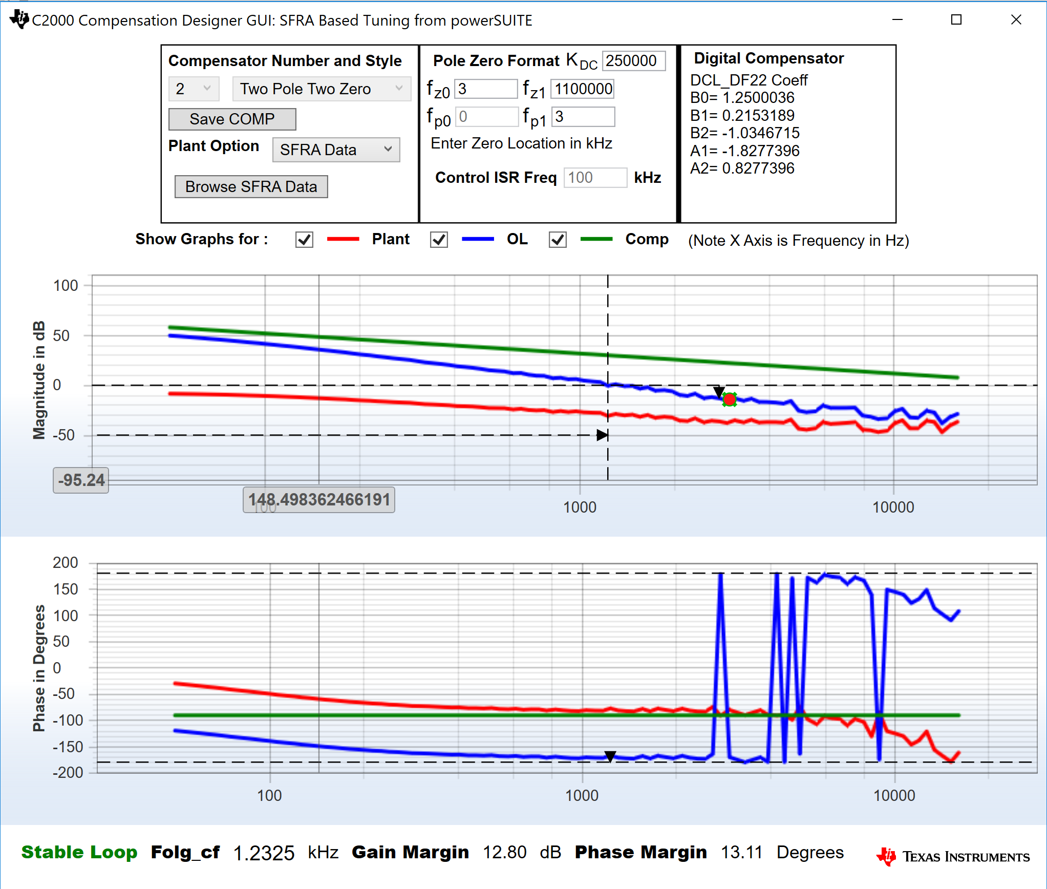
. - The compensation designer will then launch and prompt the user to select a valid SFRA data file. Import the SFRA data from the run in Lab 1 for the current loop, into the compensation designer to design a two-pole, two-zero compensator. It is good to keep more margins during this iteration of the design to ensure that when the loop is closed, the system is stable. Plant data from different runs of the SFRA can be checked to get a stable system under all conditions.
- Once satisfied with the compensator design, click on “Save COMP”. This will save the compensator values into the project.
- Close the compensation designer, return to the powerSUITE page, and save (“Ctrl-S”). This will write the new compensator values to the "settings.h" file.
- The following defines are set in the "settings.h" file for this build. These will be set by the powerSUITE page automatically; otherwise, edit the page manually.
Figure 50. Compensator Design With SFRA Based Plant Measurement for the Current Loop, Lab 3

NOTE
The tuning is carried out in DF22 fashion; however, we run the DF13 in the software. This is done because soft-starting the DF13 is easier, whereas not possible with the DF22 structure. The coefficients in both cases remain the same. At the writing of this document, the DF12 structure is not available in DCL.
#if CLLLC_LAB_NO == 3
#define CLLLC_INCR_BUILD 2
#define CLLLC_CONTROL_MODE CLLLC_CURRENT_MODE
// 0 means check with resistive load
#define CLLLC_SEC_CONNECTED_IN_BATTERY_EMULATION_MODE 0
#endif#define CLLLC_SFRA_TYPE       CLLLC_SFRA_CURRENT