TIDUEZ8C december 2022 – june 2023
2.3.2.2 High-Voltage Measurement
The high bus-voltage value is required to calculate the isolation leakage current and isolation barrier resistances. The bus voltage monitoring is an optional feature to the insulation monitoring AFE, as in low-voltage distribution systems, the bus voltage is monitored for loop compensation features. If the insulation monitoring feature is not a standalone design, and the analog front end is integrated into the power conversion stage or the central unit of the system, the bus voltage monitoring feature does not have to be duplicated.
In reference designs such as TIDA-01541, TI’s isolated amplifiers are used to perform these measurements. The new AMC3330 is specifically designed for HV measurements because the device provides reinforced isolation, high-input impedance, 2-V input range, and integrated DC-to-DC to avoid external supply on the hot side.
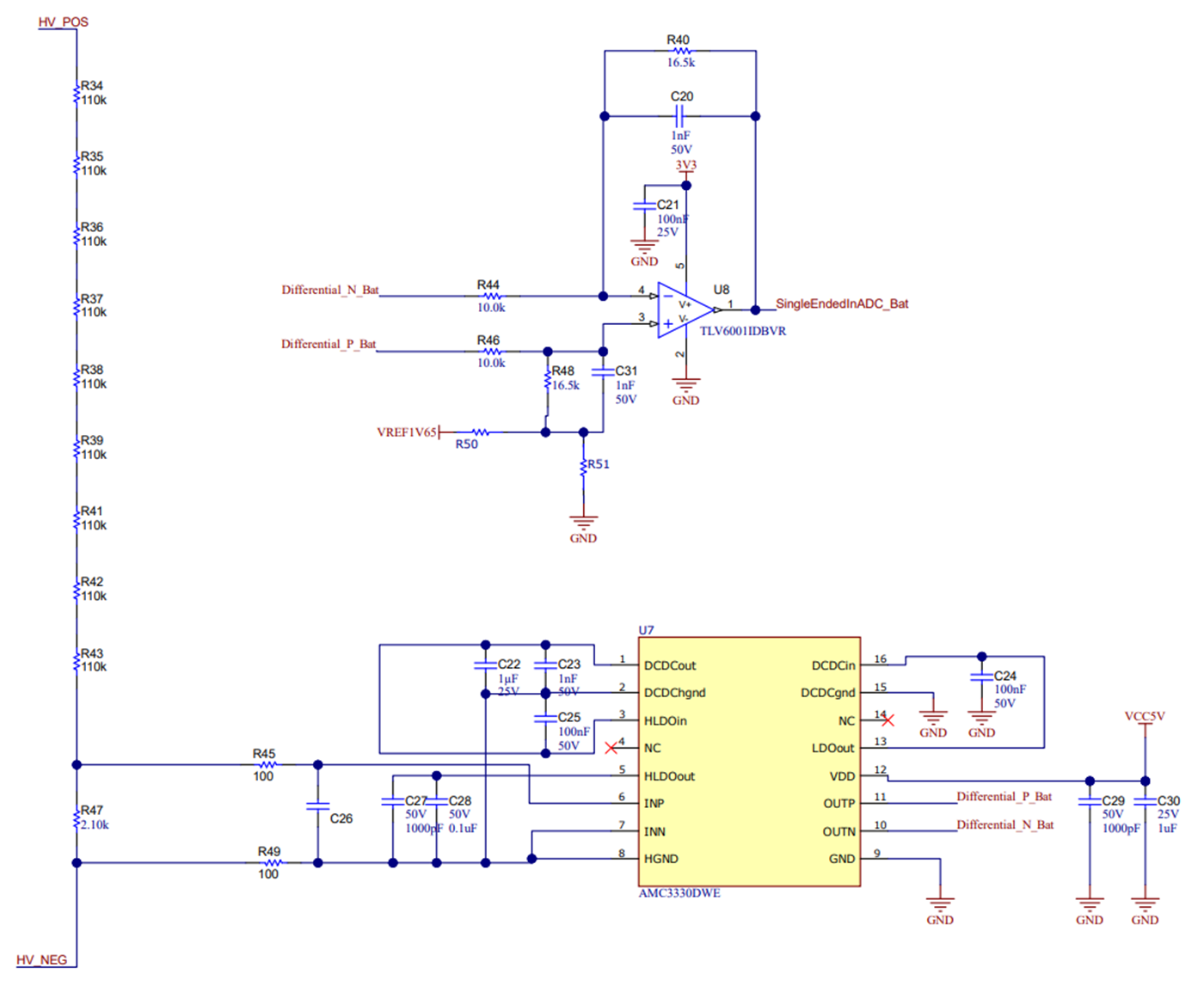
As Figure 2-11 shows, the RinAMC,DC (R47) monitoring resistor is placed in series to a high-ohmic potential divider network (R34, R35, R36, R37, R38, R39, R41, R42, R43). Voltage measurements are performed with the floating ground of the AMC3330. The AMC3330 can measure a bidirectional signal of ±1 V. In EVSE and solar string inverters, bus voltages are only in the positive range, so the usable range of the AMC3330 is +1 V. A potential divider network must be chosen in such a way that the voltage drop in shunt resistance must be ≤ 1 V at the maximum bus voltages. The TLV6001 device is used to amplify the signal range and give a single-ended output to an MCU or logic interface, see Section 2.3.2.1 for further details.
Equation 20 is a simple equation that does not consider the influences of bias currents or offset voltages, which can lead to deviations in measurements.
where
- VOut,DC(TLV6001) is the output voltage measured by the ADC or relevant device from the output of the TLV6001 in the bus voltage measurement path
- RST,DC is the sum of the series resistors from positive to negative bus voltage
- GainAMC3330 is the gain of the AMC3330 internal circuit
- GainDif2Sing,DC is the gain set by the external resistors for the TLV6001 circuit
 Figure 2-11 Schematic High-Voltage Bus
Monitoring
Figure 2-11 Schematic High-Voltage Bus
MonitoringTo enable the insulation monitoring for AC unearthed systems, the reference design gives the option of bringing the REF2033 Vref / 2 as common-mode voltage to the differential-to-single-ended conversion. Hence, when evaluating in AC line systems, a jumper enables the design to shift up the common-mode voltage and the negative side of the wave is brought at the input of the ADC. The user can evaluate in AC systems by changing the common-mode voltage reference jumper and the resistors gain accordingly.