SBVU070B September 2021 – August 2022 TPS7A94
1 Abstract
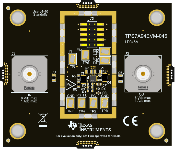
 Figure 1-1 TPS7A94EVM-046 Evaluation
Module
Figure 1-1 TPS7A94EVM-046 Evaluation
ModuleThis user's guide describes the operational use of the TPS7A94EVM-046 evaluation module (EVM) as a reference design for engineering demonstration and evaluation of the TPS7A9401DSC, an ultra-low noise, ultra-high PSRR, RF low-dropout (LDO) linear regulator. Included in this user's guide are setup and operating instructions, thermal and layout guidelines, a printed circuit board (PCB) layout, a schematic diagram, and a bill of materials (BOM).
Throughout this document the terms demonstration kit, evaluation board, and evaluation module are synonymous with the TPS7A94EVM-046.