SLAA970 October 2020 AFE7444
Application Brief
Introduction
Applications such as RADAR typically have multi-channel high speed signal chains for digital beamforming and MIMO. The analog signal chain consists of high speed data converters requiring multiple power rails (1 V, ±1.8, +3.3 V) and total power sometimes > 10 W. Since the total channel count can exceed 1000, it is paramount to increase the efficiency and improve the power consumption of the system.
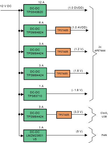 Figure 1-1 Typical Power Tree for
AFE7444
Figure 1-1 Typical Power Tree for
AFE7444Figure 1 shows a Point-of-Load (PoL) power supply for the AFE7444 includings DC/DC regulators followed by a low noise LDO. An LDO filters the switching noise to maximize the signal chain performance. However, LDOs increase the total power consumption of the system due to the dropout and makes the system inefficient. Also, the large power dissipation in dense systems like RADAR makes the challenge of thermal dissipation difficult to manage. However, eliminating the LDO could degrade the signal chain performance.
Impact of DC/DC switching noise on ADC performance
Switching noise from the power supply can directly couple to the ADC input path or to the clock path. Therefore, spurs at frequencies FDC/DC and Fin ± FDC/DC are observed in the output spectrum. Figure 2 shows coupling paths of switching noise and its effect on the ADC output spectrum. For more information, see the Designing a modern power supply for RF sampling converters analog application journal.
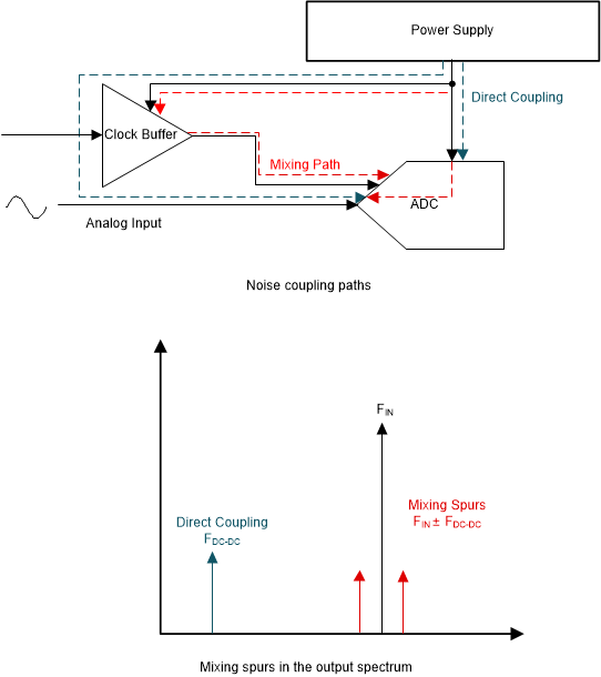 Figure 1-2 Power Supply Impact on High
Speed Signal Chain
Figure 1-2 Power Supply Impact on High
Speed Signal ChainUsing ferrite bead to eliminate the DC/DC spur noise
Figure 3 shows receiver performance of the AFE7444 when only a DC/DC regulator is used. Once LDO is removed from analog supplies, spurs at frequencies (Fin ± 500 kHz) appears in the spectrum, resulting in SNR and SFDR degradation. Note all DC/DC converters are operating at 500 kHz.
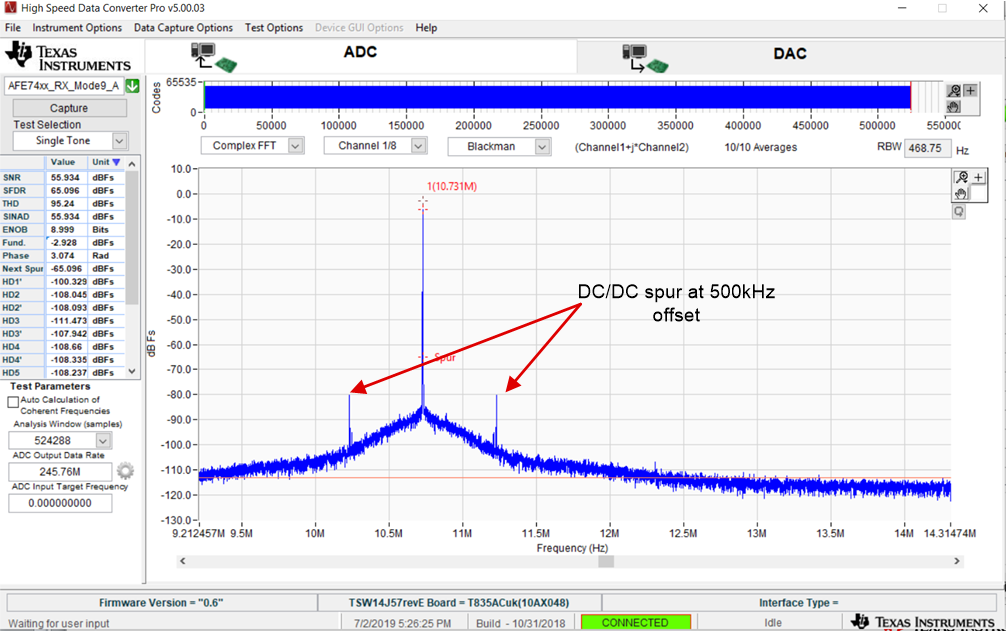 Figure 1-3 RX Performance after Removing
LDO from Analog Power Rails
Figure 1-3 RX Performance after Removing
LDO from Analog Power RailsSince the impact of DC/DC noise is predominantly limited to the switching frequency and its harmonics, a filter can be used in place an LDO. Figure 4 shows the filter used on this design.
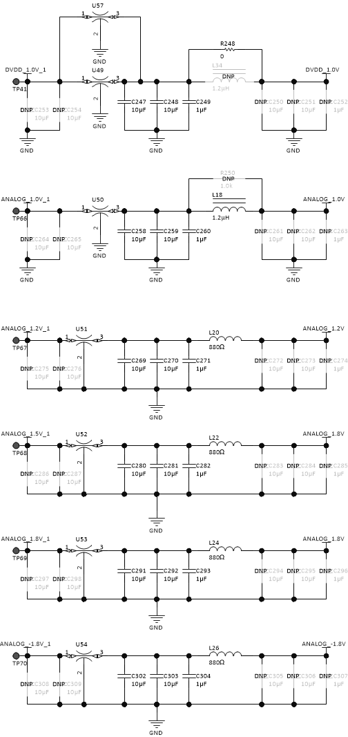 Figure 1-4 Filters on Power
Supply
Figure 1-4 Filters on Power
SupplyFigure 5 shows the RX performance after adding filters on the analog supplies. It is seen that DC/DC spurs becomes unnoticeable after addition of the small filter at the analog power rails. The AC performance achieved is close to EVM performance that uses LDO for analog supplies. See the Low-noise power-supply reference design maximizing performance in 12.8-GSPS data acquisition systems for more details
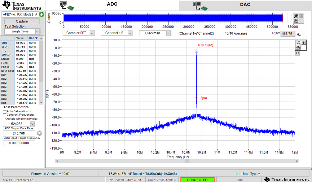 Figure 1-5 RX Performance After Adding
Filters at Analog Power Rails
Figure 1-5 RX Performance After Adding
Filters at Analog Power RailsConclusion
It has been shown that LDOs can be replaced with filters while preserving the original signal chain performance. The removal of the LDOs results in total power savings greater than > 2 W
| Power rail |
Mode 9 Current consumption |
LDO power dissipation (500 mV dropout) |
|---|---|---|
| 1 V DVDD | 4.1 A | N/A |
| 1 V VDDA | 1.9 A | 0.95 W |
| 1.2 V | 1 A | 0.5 W |
| 1.8 V | 1.5 A | 0.75 W |
| -1.8 V | 0.3 A | 0.15 W |
| Total power savings | 2.35 W | |