SLVAF91 October 2021 TPS1HB08-Q1
1 Application Brief
It is easy to underestimate the challenge of driving bulbs. In the automotive industry, many cars are still fitted with incandescent or halogen bulbs. While there is a push to move to LED and Laser lights, these bulbs are still used because of their ease of access, lack of complex driving or control and allow consumers to easily make low cost repairs when needed. With these benefits also come certain difficulties. Incandescent and halogen bulbs both produce light by heating up a filament. The challenge arises with the amount of current required to heat up the bulb so that it glows and produces light. These bulbs will have to turn on instantaneously in all conditions rated for the automobile.
Electrical Model
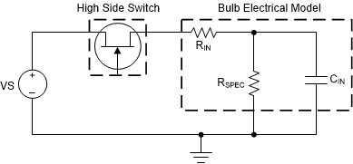
The construction of an incandescent or halogen bulb involves a high-power capable filament enclosed in a sealed transparent container filled with an inert gas to prevent oxidation. Electrically, it can be modeled as shown in Figure 1-1
 Figure 1-1 Electrical Model of a Halogen or Incandescent Bulb
The Figure 1-1 model does not consider any non-idealities in the circuit such as the inductance of the power cable connecting the switch to the bulb which can have an inductance ranging from 1uH to 5uH. In this setup, CIN and RIN are the inrush capacitance and resistance while RSPEC is the filament resistance once the bulb is heated up and on. Power dissipated through RSPEC is in the form of heat and light. The inrush capacitance for incandescent or halogen bulbs can be very large.
Since the filament is essentially a low resistance wire, low ambient temperatures will also result in larger inrush events when compared to that at room temperature. Overall, this results in a situation where the inrush spike can be significantly larger than the DC current taken to maintain the light output. Therefore, the switch used must be capable of handling these high inrush currents without turning off due to excessive current or integrated protection features like current limit. TI offers low resistance high side switches to meet these various requirements while allowing easy control of the system.
TI High Side Switch Protection
The inrush phase of bulb driving is similar to a short circuit fault. The exception for bulbs is that this current must pass through the filament before it can heat up and produce light. Blocking of this current will result in a failure mode that includes the bulb taking a very long time to turn on or never turning on at all. Depending on the High Side Switch chosen, the overcurrent protection either clamps current of the output or immediately shuts off the device.
To effectively turn on a bulb, it is recommended to select a device that uses the immediate shutoff feature and has a wide operating range. Another similar concern is the integrated thermal shutdown of the device. The large inrush even can lead to the junction temperature spiking higher than the turnoff point. This is because if the inrush current is clamped or not allowed to pass through to the bulb in full, the filament in the bulb will not heat up sufficiently before the device hits thermal shutdown.
A good option is to use TPS1HB08-Q1. This high side switch has an on resistance of 8mOhm and has integrated overcurrent protection in the form of an immediate shutoff. The device offers three variants with the ability for the user to set the limit at various values. For lower wattage bulbs, Version A and B can be used. For higher wattage bulbs on the order of 65 W or more, TI also offers a Version F which has an internally set high current limit.
Driving Bulb Loads in Different Operating Conditions
The same bulb load can have different behaviors depending on the operating conditions in which it is driven. The switch chosen to drive bulb loads has to therefore account for extreme use cases that are brought about by the use of the vehicle and the weather.
The two major conditions that describe if a bulb can be successfully driven by a switch are (i) if the switch is at high ambient temperature due to heat produced by the engine while the bulb is at a nominal temperature and (ii) if the switch is at a typical temperature while the bulb is at an extreme cold ambient temperature.
In the first case, the concern is that the heat produced by the inrush event is enough to trigger the integrated protection in the switch. If this overtemperature protection is triggered, the switch will not turn on or will exhibit a delayed turn on event as the inrush current has not heated the filament up to produce light.
In the second case, the temperature of the filament is low resulting in a larger inrush current. The concern here is brought about by the current limit and thermal shutdown. If the device triggers a current limit or thermal shutdown protections, then the junction has to cool down sufficiently before it will retry. This may lead to the bulb not turning on as during the shutdown time, the filament is cooling back down to ambient temperature.
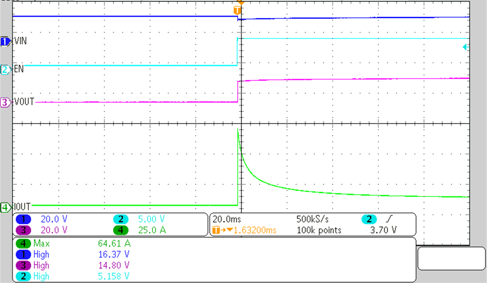
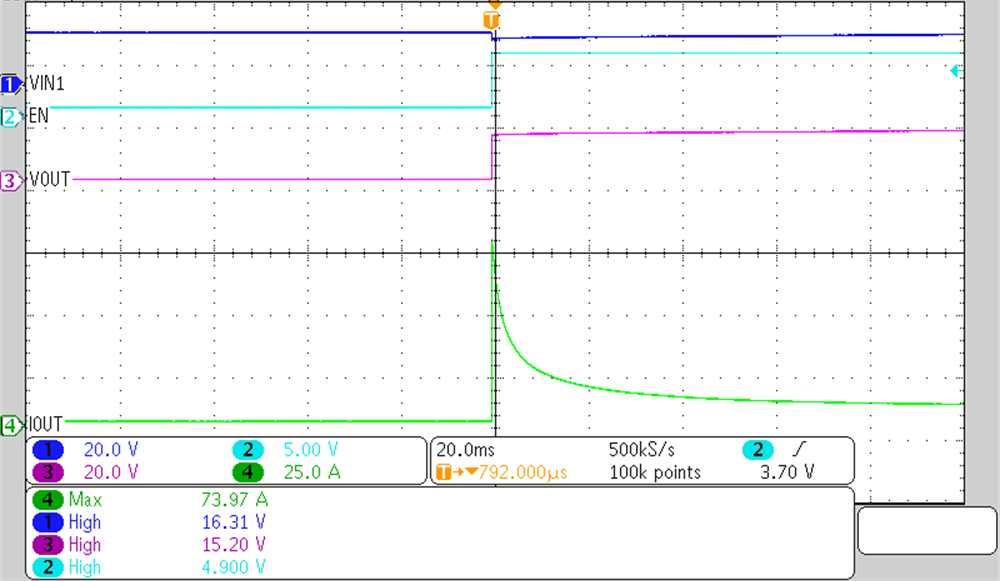
Figure 1-2 describes the successful operation with TPS1HB08F-Q1 of a H9 65-W bulb under device temperature of 105 °C and a bulb temperature at 25 °C. Figure 1-3 describes the successful operation with TPS1HB08F-Q1 of a H9 65 W under device temperature of 25 °C and a bulb temperature of -40 °C. The inline inductance is less than 2 uH and the inline resistance is less than 60 mOhm.
 Figure 1-2 Bulb Inrush Event with Device Under High Ambient Temperature
 Figure 1-3 Bulb Inrush Event with Bulb Under Low Ambient Temperature
Summary
TI’s High Side Switch portfolio is able to drive bulbs at various loads while accounting for all the listed concerns and provides robust protection. Table 1-1 describes the recommended switch for a single bulb load at various wattages driven at 16 V with the bulb under an ambient temperature of -40 °C and the device at 25 °C.
| Bulb Wattage | Expected Inrush Current | TI Part Recommendation |
|---|---|---|
| <10 W | <14.9 A | TPS1HB35F-Q1 |
| >10 W to <35 W | <48.4 A | TPS1HB16F-Q1 |
| >35 W to <65 W | <73.9 A | TPS1HB08F-Q1 |