SLVAFC3 March 2022 TPS61022
1 Application Brief
Introduction
Most of TI’s TPS61xxx low-voltage boost converters equip PSM (Power Save Mode) to help increase light-load efficiency. However, usually the output ripple can be higher than PWM when it is heavy load. In addition, the load current threshold between PSM and PWM is not intuitively written in the data sheet. These bring difficulty and confusion designing the circuitry in applications that are sensitive to output voltage ripple. This application brief shares a typical operating mechanism of PSM in TPS61022, and how to figure out load threshold between PSM and PWM for most of TPS61xxx boost converters.
A Typical Operating Mechanism of PSM
Figure 1-1 illustrates a simplified mechanism of PFM (Pulse Frequency Modulation) which has been used in TPS61022. PFM is one type of PSM and helps increase light load efficiency. TPS61022 uses adaptive constant on-time valley current control. As can be seen, initially output current drops, as a result, output voltage rises. Internal error amplifier decreases inductor valley current to response increased output voltage. However, when inductor valley current drops to low clamp, error amp is clamped and inductor valley current does not drop further.
As the error amp is clamped, there is always energy larger than load demanded sourcing to output capacitors. Therefore, output voltage keeps charging up. When FB hits PFM reference, internal comparator sets both FETs to be OFF after rising delay TDLY_R. When FB drops below PFM reference, comparator releases both FETs after falling delay TDLY_F. After that, the clamped EA ramps inductor valley to the low clamp and output voltage increases. The delay is not intentionally designed and is unnecessarily considered in real design. Output ripple in PFM has been simulated across corner cases to be 30mV (typ.) and 50mV (max) under data sheet’s recommended operating conditions.
Figure 1-2 illustrates mechanism of how TPS61022 exits PFM. If load suddenly increases, output voltage drops and inductor current in low clamp cannot hold output voltage anymore. Error amp runs inductor current up. When inductor valley current is above 170 mA (typ.), PFM quits and TPS61022 enters PWM utilizing new PWM reference.
Load Threshold between PSM and PWM for TPS61xxx Converters
Equation 1 demonstrates how to calculate the load current threshold between PFM and PWM for TPS61022.
Inside equation:
VIN is input voltage;
VOUT is output voltage;
IL_VALLEY is threshold valley current when device knows to switch mode;
∆IL is inductor current ripple;
η is efficiency.
Equation 2 gives inductor current ripple calculation. Therefore, the load current threshold between PFM and PWM depends on input voltage, output voltage, inductor value, internal valley current threshold and efficiency.
Another quicker way is to use load regulation curve in data sheet. This way is more intuitive to know the load threshold without calculation than calculation method, and is effective for most of TPS61xxx boost converters.
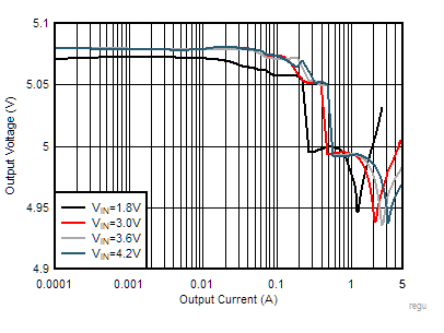
In data sheet, we can find load regulation curve which tells relations between output voltage and load current. The threshold between PSM and PWM has been implied inside curves. Figure 1-3 represents TPS61022’s load regulation in Auto PFM among different input voltage. The data was tested under typical condition at 25ºC. It can be seen that output voltage is initially above 5 V in light load. After output current increases above 200 mA, output voltage drops to 5 V. According to Auto PFM mechanism, when output voltage is higher than 5 V with 1% offset, TPS61022 operates at Auto PFM mode. When output voltage is exactly at 5 V, this means device is at PWM. Therefore, the load threshold is at where output voltage jumps from a PFM value to nominal value.
Taking two examples in TPS61022’s load regulation data, in terms of VIN=1.8V curve, VOUT drops to 5 V when output current is about 250 mA, so the device enters PWM if load is above 250 mA. In addition, when VIN is 4.2 V, VOUT drops to 5 V after output current increases to 500 mA. Therefore, threshold changes to 500 mA.
 Figure 1-3 TPS61022 Load Regulation in Auto PFM
Conclusion
- In TPS61022’s Auto PFM mode, internal error amplifier no longer regulates output voltage. Comparator will take the control to turn off FETs until FB ramps above PFM reference;
- Load current threshold where device switches from PSM to PWM can be found in load regulation curve in data sheet;
- Load current threshold where device switches from PSM to PWM is not a fixed value, it is influenced by input voltage, output voltage, inductor value, PSM mechanism and efficiency.