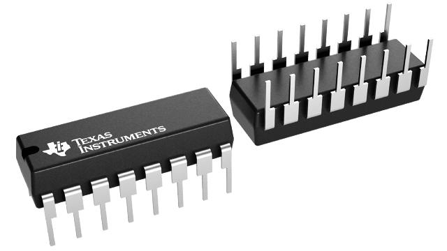
16-pin (N) package image

CD74HCT670E ACTIVE

High Speed CMOS Logic 4-by-4 Register File

open-in-new View alternates

Pricing

Qty Price
+

Quality information

Rating Catalog
RoHS Yes
REACH Yes
Lead finish / Ball material NIPDAU
MSL rating / Peak reflow Level-NC-NC-NC
Quality, reliability
& packaging information

Information included:

  • RoHS
  • REACH
  • Device marking
  • Lead finish / Ball material
  • MSL rating / Peak reflow
  • MTBF/FIT estimates
  • Material content
  • Qualification summary
  • Ongoing reliability monitoring
View or download
Additional manufacturing information

Information included:

  • Fab location
  • Assembly location
View

Export classification

*For reference only

  • US ECCN: EAR99

Packaging information

Package | Pins PDIP (N) | 16
Operating temperature range (°C) -55 to 125
Package qty | Carrier 25 | TUBE

Features for the CD74HCT670

  • Simultaneous and Independent Read and Write Operations
  • Expandable to 512 Words of n-Bits
  • Three-State Outputs
  • Organized as 4 Words x 4 Bits Wide
  • Buffered Inputs
  • Typical Read Time = 16ns for ’HC670 VCC = 5V, CL = 15pF, TA = 25°C
  • Fanout (Over Temperature Range)
    • Standard Outputs...10 LSTTL Loads
    • Bus Driver Outputs...15 LSTTL Loads
  • Wide Operating Temperature Range... –55°C to 125°C
  • Balanced Propagation Delay and Transition Times
  • Significant Power Reduction Compared to LSTTL Logic ICs
  • HC Types
    • 2V to 6V Operation
    • High Noise Immunity: NIL = 30%, NIH = 30% of VCC at VCC = 5V
  • HCT Types
    • 4.5V to 5.5V Operation
    • Direct LSTTL Input Logic Compatibility, VIL = 0.8V (Max), VIH = 2V (Min)
    • CMOS Input Compatibility, Il ≤ 1µA at VOL, VOH

Description for the CD74HCT670

The ’HC670 and CD74HCT670 are 16-bit register files organized as 4 words x 4 bits each. Read and write address and enable inputs allow simultaneous writing into one location while reading another. Four data inputs are provided to store the 4-bit word. The write address inputs (WA0 and WA1) determine the location of the stored word in the register. When write enable (WE\) is low the word is entered into the address location and it remains transparent to the data. The outputs will reflect the true form of the input data. When (WE\) is high data and address inputs are inhibited. Data acquisition from the four registers is made possible by the read address inputs (RA1 and RA0). The addressed word appears at the output when the read enable (RE\) is low. The output is in the high impedance state when the (RE\) is high. Outputs can be tied together to increase the word capacity to 512 x 4 bits.
Pricing

Qty Price
+

Carrier options

You can choose different carrier options based on the quantity of parts, including full reel, custom reel, cut tape, tube or tray.

A custom reel is a continuous length of cut tape from one reel to maintain lot- and date-code traceability, built to the exact quantity requested. Following industry standards, a brass shim connects an 18-inch leader and trailer on both sides of the cut tape for direct feeding into automated assembly machines. TI includes a reeling fee for custom reel orders.

Cut tape is a length of tape cut from a reel. TI may fulfill orders using multiple strips of cut tapes or boxes to satisfy the quantity requested.

TI often ships tube or tray devices inside a box or in the tube or tray, depending on inventory availability. We pack all tapes, tubes or sample boxes according to internal electrostatic discharge and moisture-sensitivity-level protection requirements.

Learn more

Lot and date code selection may be available

Add a quantity to your cart and begin the checkout process to view the options available to select lot or date codes from existing inventory.

Learn more