SLPS582B July 2016 – March 2024 CSD19538Q2
PRODUCTION DATA
- 1
- 1Features
- 2Applications
- Description
- 3Specifications
- 4Device and Documentation Support
- 5Revision History
- 6Mechanical, Packaging, and Orderable Information
Package Options
Mechanical Data (Package|Pins)
- DQK|6
Thermal pad, mechanical data (Package|Pins)
- DQK|6
Orderable Information
3.2 Thermal Information
TA = 25°C (unless otherwise stated)
| THERMAL METRIC | MIN | TYP | MAX | UNIT | |
|---|---|---|---|---|---|
| RθJC | Junction-to-case thermal resistance(1) | 6.2 | °C/W | ||
| RθJA | Junction-to-ambient thermal resistance(1)(2) | 65 | °C/W | ||
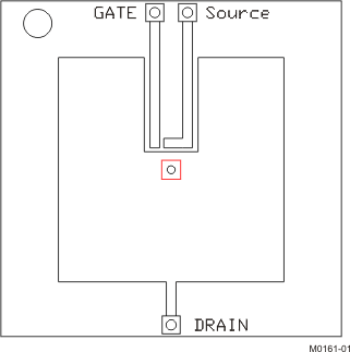
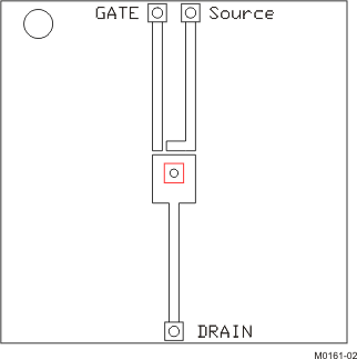
(1) RθJC is determined with the device mounted on a 1in2
(6.45cm2), 2oz (0.071mm) thick Cu pad on a 1.5in × 1.5in (3.81cm
× 3.81cm), 0.06in (1.52mm) thick FR4 PCB. RθJC is specified by
design, whereas RθJA is determined by the user’s board design.
(2) Device mounted on FR4 material with 1in2 (6.45cm2), 2oz
(0.071mm) thick Cu.

| Max RθJA = 65°C/W when mounted on 1in2 (6.45cm2) of 2oz (0.071mm) thick Cu. | 
| Max RθJA = 250°C/W when mounted on a minimum pad area of 2oz (0.071mm) thick Cu. |