SLOS754C June 2012 – August 2016 DRV2603
PRODUCTION DATA.
- 1 Features
- 2 Applications
- 3 Description
- 4 Revision History
- 5 Pin Configuration and Functions
- 6 Specifications
- 7 Parameter Measurement Information
-
8 Detailed Description
- 8.1 Overview
- 8.2 Functional Block Diagram
- 8.3
Feature Description
- 8.3.1 Supply Voltage Rejection for Constant Vibration Strength
- 8.3.2 Low-Voltage Control Logic for Constant Vibration Strength
- 8.3.3 Thermal Protection
- 8.3.4 Overcurrent Protection
- 8.3.5 Linear Resonance Actuators (LRA)
- 8.3.6 Auto Resonance Engine for LRA
- 8.3.7 Eccentric Rotating Mass Motors (ERM)
- 8.3.8 Edge Rate Control
- 8.4 Device Functional Modes
- 9 Application and Implementation
- 10Power Supply Recommendations
- 11Layout
- 12Device and Documentation Support
- 13Mechanical, Packaging, and Orderable Information
Package Options
Mechanical Data (Package|Pins)
- RUN|10
Thermal pad, mechanical data (Package|Pins)
- RUN|10
Orderable Information
11 Layout
11.1 Layout Guidelines
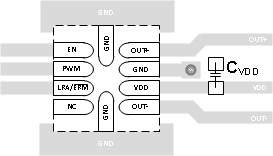
The following list contains guidelines for the DRV2603 layout:
- The decoupling capacitor for the power supply should be placed close to the device pin (VDD).
- The supply ground should be connected to all GND pins
11.2 Layout Example
Figure 19 shows the recommended layout for the DRV2603.
 Figure 19. DRV2603 Layout Example