SLLSEK2A June 2014 – March 2017 DRV8846
PRODUCTION DATA.
- 1 Features
- 2 Applications
- 3 Description
- 4 Revision History
- 5 Pin Configuration and Functions
- 6 Specifications
- 7 Detailed Description
- 8 Application and Implementation
- 9 Power Supply Recommendations
- 10Layout
- 11Device and Documentation Support
- 12Mechanical, Packaging, and Orderable Information
Package Options
Mechanical Data (Package|Pins)
- RGE|24
Thermal pad, mechanical data (Package|Pins)
- RGE|24
Orderable Information
7.3.4 Decay Mode
After the chopping current threshold is reached, the drive current is interrupted, but due to the inductive nature of the motor, current must continue to flow for some period of time (called recirculation current). To handle this recirculation current, the H-bridge can operate in two different states, fast decay or slow decay (or a mixture of fast and slow decay).
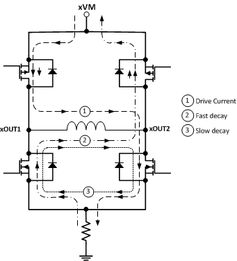
In fast-decay mode, after the PWM chopping current level is reached, the H-bridge reverses state to allow winding current to flow through the opposing FETs. As the winding current approaches 0, the bridge is disabled to prevent any reverse current flow. For fast-decay mode, see number 2 in Figure 7.
In slow-decay mode, winding current is recirculated by enabling both of the low-side FETs in the bridge. For slow-decay mode, see number 3 in Figure 7.
 Figure 7. Decay Modes
 The DRV8846 supports fast, slow, mixed, and smart tune modes. With stepper motors, the decay mode is chosen for a given stepper motor and operating conditions to minimize mechanical noise and vibration.
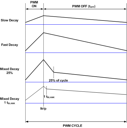
In mixed decay mode, the current recirculation begins as fast decay, but at a fixed period of time (determined by the state of the DEC1 and DEC0 pins shown in Table 7) the current recirculation switches to slow decay mode for the remainder of the fixed PWM period. Note that the DEC1 and DEC0 pins are tri-level inputs; these pins can be driven logic low, logic high, or high-impedance (Z).
Figure 8 shows the current waveforms in slow, fast, and 25% and 1 tBLANK mixed decay modes.
 Figure 8. Decay Behavior
 Table 7. Decay Pins Configuration
| DEC1 | DEC0 | Decay Mode (Increasing Current) | Decay Mode (Decreasing Current) |
|---|---|---|---|
| 0 | 0 | Slow decay | Slow decay |
| 0 | Z | Slow decay | Mixed decay: 25% fast |
| 0 | 1 | Slow decay | Mixed decay: 1 tBLANK |
| Z | 0 | Mixed decay: 1 tBLANK | Mixed decay: 1 tBLANK |
| Z | Z | Mixed decay: 50% fast | Mixed decay: 50% fast |
| Z | 1 | Mixed decay: 25% fast | Mixed decay: 25% fast |
| 1 | 0 | Slow decay | Mixed decay: 50% fast |
| 1 | Z | Slow decay | Mixed decay: 12.5% fast |
| 1 | 1 | Slow decay | Fast decay |
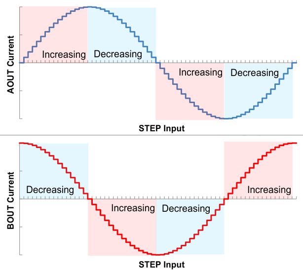
Figure 9 shows increasing and decreasing current. When current is decreasing, the decay mode used is fast, slow, or mixed as commanded by the DEC1 and DEC0 pins. Three DEC pin selections allow for mixed decay during increasing current.
 Figure 9. Increasing and Decreasing Current
 Smart tune mode simplifies the decay mode selection by dynamically changing to adjust for current level, step change, supply variation, BEMF, and load. To enable smart tune mode, pull the ADEC pin to logic high and pull DEC0 and DEC1 pins to logic high. The state of the ADEC pin is only evaluated when exiting sleep mode. (ADEC pin must be high before exiting sleep to enable smart tune mode.)
Smart tune adjusts the time spent in fast decay to minimize current ripple and quickly adjust to current-step changes. If the drive time is longer than the minimum (tBLANK), in order to reach the current trip point, the decay mode applied is slow decay (see Figure 10).
 Figure 10. Smart Tune – Slow Decay Operation
 When the minimum drive time (tBLANK) provides more current than the regulation point, fast decay of 1- tBLANK is applied. If the second drive period also provides more current than the regulation point, fast decay of 2 tBLANK is applied. If a third (or more) consecutive period provides more current than the regulation point, fast decay using 25% of tOFF time is applied. When the minimum drive time is insufficient to reach the current regulation level, slow decay is applied until the current exceeds the current reference level (see Figure 11).
 Figure 11. Smart Tune – Mixed Decay Operation
 Figure 12 shows a case for smart tune where a step occurs. The system starts with 1 tBLANK of fast decay and works up to 25% of tOFF time for fast decay until the current is regulated again.
 Figure 12. Smart Tune – Step Operation