SBOS035B december 1995 – may 2023 INA2128
PRODUCTION DATA
- 1
- 1Features
- 2Applications
- 3Description
- 4Revision History
- 5Pin Configuration and Functions
- 6Specifications
- 7Application and Implementation
- 8Device and Documentation Support
- 9Mechanical, Packaging, and Orderable Information
Package Options
Mechanical Data (Package|Pins)
- DW|16
Thermal pad, mechanical data (Package|Pins)
- DW|16
Orderable Information
7.2.1 Setting The Gain
Gain of the INA2128 is set by connecting a single external resistor, RG, connected as shown:
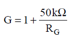
Commonly-used gains and resistor values are shown in Figure 7-1.
The 50 kΩ term in Equation 1 comes from the sum of the two internal feedback resistors, A1 and A2. These on-chip metal film resistors are laser-trimmed to accurate absolute values. The accuracy and temperature coefficient of these resistors are included in the gain accuracy and drift specifications of the INA2128.
The stability and temperature drift of the external gain setting resistor, RG, also affects gain. RG’s contribution to gain accuracy and drift can be directly inferred from the gain equation (1). Low resistor values required for high gain can make wiring resistance important. Sockets add to the wiring resistance which will contribute additional gain error in gains of approximately 100 or greater.